Ethylene cracking furnace cracking gas pipeline decoking system and cracking gas pipeline anti-coking and decoking method

A technology of ethylene cracking furnace and cracking gas, which is applied in the direction of cracking, hydrocarbon cracking to hydrocarbon, non-catalytic thermal cracking, etc. It can solve the problems of filter clogging and multi-stage coke catcher cost increase, so as to reduce investment costs and solve switch Difficult, prolonged operating cycle effects

Active Publication Date: 2021-03-23
SINOPEC ENG +1
View PDF3 Cites 0 Cited by
  • Summary
  • Abstract
  • Description
  • Claims
  • Application Information

AI Technical Summary

Problems solved by technology

[0005] One anti-coking method in the ethylene plant is to set up a decoking device for the quenching oil system. At the outlet of the oil washing tower and before the quenching oil circulation pump, a filter is installed to capture coke particles or a hydrocyclone separator is installed to reduce the coke particles entering Subsequent quench oil circulation system, but the filter will often clog and thus require frequent cleaning
[0006] Another anti-coking method for the cracked gas pipeline in the ethylene plant is to install a multi-stage trapping device in the cracked gas pipeline of the multi-stage quenching system. One of the defects of this method is that it does not prevent the large valve of the cracked gas by adjusting the direction of the cracked gas pipeline. Coking at the place, and the multi-stage coking device installed in the pyrolysis gas pipeline increases the cost

Method used


Image

  • Ethylene cracking furnace cracking gas pipeline decoking system and cracking gas pipeline anti-coking and decoking method
  • Ethylene cracking furnace cracking gas pipeline decoking system and cracking gas pipeline anti-coking and decoking method
  • Ethylene cracking furnace cracking gas pipeline decoking system and cracking gas pipeline anti-coking and decoking method

Examples


Embodiment 1

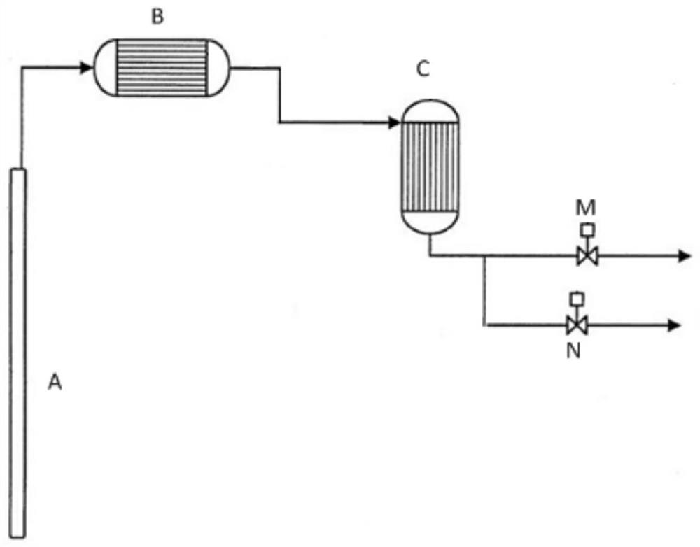
[0057] use as Figure 5 The coke prevention layout trend diagram of cracking gas pipeline decoking system of ethylene cracking furnace is shown for decoking of cracking gas pipeline. When the cracking furnace is in normal operation and cracking gas phase raw materials, the high-temperature cracking gas from the furnace tube in the radiant section is cooled by all levels of quenching heat exchangers and then moves horizontally to the front of the cracking gas valve. The pipeline where the cracking gas valve is located is from the horizontal cracking gas pipeline. The top is extracted upwards, and the cracked gas passes through the upwardly drawn pipeline (branch 1) and then enters the downstream system through the horizontal arrangement section equipped with a large cracked gas valve. This upward extraction method can make the coke particles generated in the furnace tube and quenching heat exchanger during normal operation gather at the blind end reserved for the pyrolysis gas ...

Embodiment 2

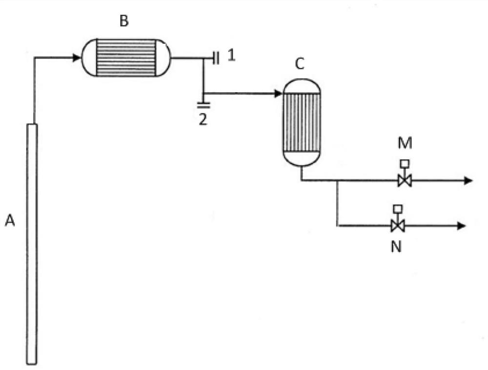
[0059] use as Figure 6 The coke prevention layout trend diagram of cracking gas pipeline decoking system of ethylene cracking furnace is shown for decoking of cracking gas pipeline. When the cracking furnace is operating normally and cracking the gas phase feedstock, with Figure 5 The difference of the provided embodiment 1 is that in the direction of the cracking gas pipeline, the coke cleaning pipeline (branch 2) where the coke cleaning valve is located is extracted from the side of the cracking gas pipeline, and is connected with the pipeline where the cracking gas large valve is located. (Branch 1) on the same side. Depend on Figure 6 It can be seen that during normal operation, the coke particles produced in the cracked gas pipeline, furnace tube and quenching heat exchanger will enter the blind end reserved for the cracked gas pipeline with potential energy, avoiding the coke particles in the cracked gas valve and coke cleaning. Buildup at the valve.

Embodiment 3

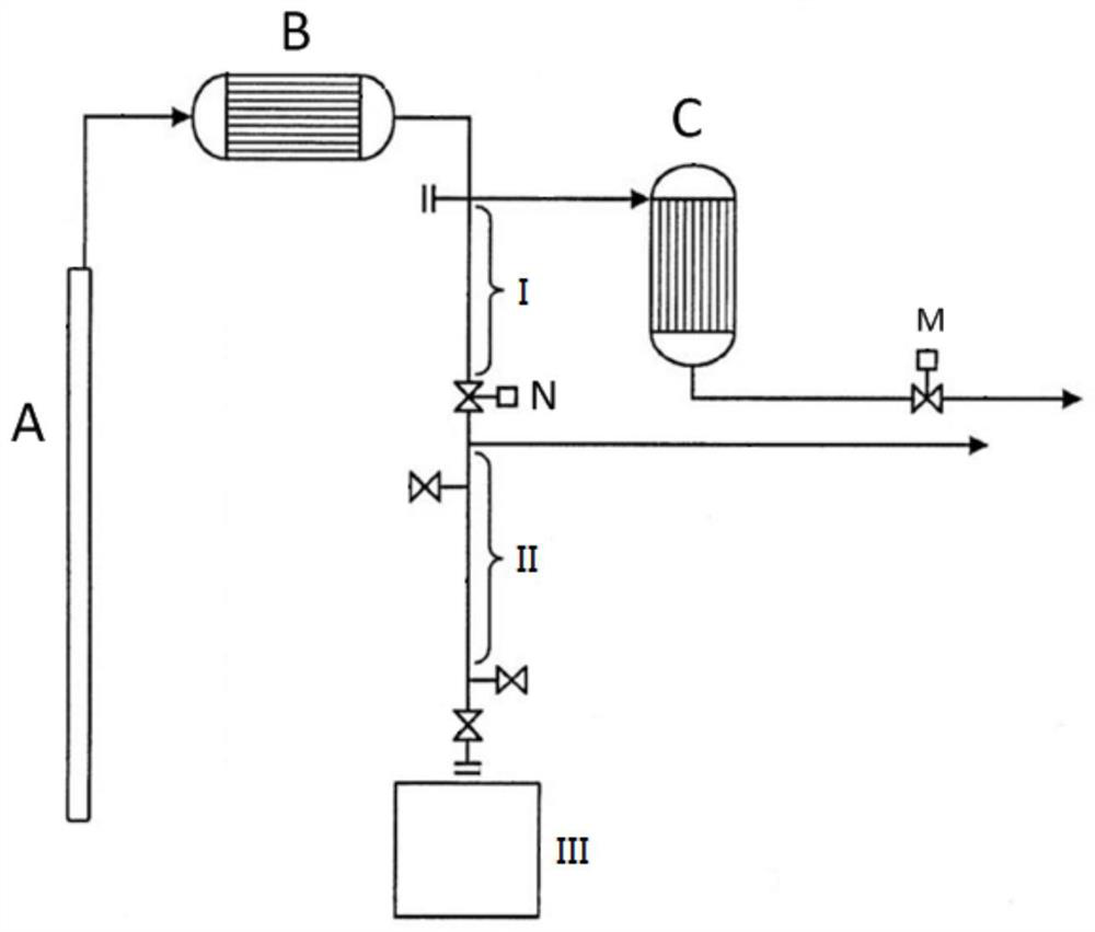
[0061] use as Figure 7 The coke prevention layout trend diagram of cracking gas pipeline decoking system of ethylene cracking furnace is shown for decoking of cracking gas pipeline. When the cracking furnace is operating normally and cracking the gas phase feedstock, with Figure 6 The difference of the provided embodiment 2 is that in the trend of the cracking gas pipeline, the coke cleaning pipeline (branch 2) where the coke cleaning valve is located is drawn upwards from the top of the cracking gas pipeline, which can avoid the normal operation of the cracking furnace When the coke particles in the pipeline accumulate in front of the coke cleaning valve, it will cause the coke cleaning valve to be blocked and difficult to open. Depend on Figure 7 It can be seen that during normal operation, the coke particles produced in the cracked gas pipeline, furnace tube and quenching heat exchanger will enter the blind end reserved for the cracked gas pipeline with potential energ...


PUM


Abstract

The invention belongs to the field of hydrocarbon processing, and relates to an ethylene cracking furnace cracking gas pipeline decoking system and a cracking gas pipeline anti-coking and decoking method. The system comprises a cracking gas pipeline, at least one coke particle trapping device and two branches sequentially arranged on the cracking gas pipeline in the material flowing direction. A first branch is used for the normal operation working condition of the cracking furnace, and a second branch is used for the decoking working condition of the cracking furnace. The first branch is a pyrolysis gas pipeline top upward extraction type or a pyrolysis gas pipeline side extraction type, a pyrolysis gas large valve is arranged on the first branch, the second branch is a pyrolysis gas pipeline top upward extraction type or a pyrolysis gas pipeline side top flat extraction type, and a decoking valve is arranged on the second branch. Coke particles can be accumulated by changing the trend of the cracking pipeline and arranging a corresponding decoking device, so that accumulation is avoided; and coke particles in a material flow returned to the hearth for burning can be reduced, andash deposition in a convection section of the cracking furnace is reduced.

Description

technical field [0001] The invention belongs to the field of hydrocarbon processing, and more specifically relates to a decoking system for cracking gas pipelines of ethylene cracking furnaces and a method for coking prevention and decoking of cracking gas pipelines using the system. Background technique [0002] With the development of the economy, the demand for hydrocarbon chemical raw materials is increasing day by day. As an important chemical raw material, ethylene is also expanding its application market. Hydrocarbon cracking to produce ethylene is the mainstream process for producing ethylene in the current market. Hydrocarbon raw materials are pyrolyzed in the radiant section of the cracking furnace to produce high-temperature pyrolysis gas, which is cooled by the quenching heat exchanger and enters the oil washing, compression and subsequent separation systems. According to the situation of different cracking raw materials, one-stage quenching or multi-stage quenc...

Claims


Application Information

Patent Timeline
IPC IPC(8): C10G9/16C07C4/04C07C11/04
CPCC10G9/16C07C4/04C10G2400/20C07C11/04
Inventor 何细藕赵永华白飞李昌力
Owner SINOPEC ENG
Why Eureka
Try Eureka