
Tin drop generating device

A technology for generating devices and tin droplets, which is applied in the directions of spraying devices, spraying devices, photolithography process exposure devices, etc. The effect of blocking, avoiding nozzle clogging, avoiding the accumulation of impurities

Active Publication Date: 2021-03-23
SHANGHAI INTEGRATED CIRCUIT EQUIP & MATERIALS IND INNOVATION CENT CO +1
View PDF20 Cites 0 Cited by
  • Summary
  • Abstract
  • Description
  • Claims
  • Application Information

AI Technical Summary

Problems solved by technology

The regular measurement and cleaning process will affect the normal use of mainstream extreme ultraviolet lithography machines, and the measurement and cleaning process is cumbersome

Method used


Image

  • Tin drop generating device
  • Tin drop generating device
  • Tin drop generating device

Examples


Embodiment Construction

[0035] The specific embodiment of the present invention will be further described in detail below in conjunction with the accompanying drawings.

[0036] It should be noted that, in the following specific embodiments, when describing the embodiments of the present invention in detail, in order to clearly show the structure of the present invention for the convenience of description, the structures in the drawings are not drawn according to the general scale, and are drawn Partial magnification, deformation and simplification are included, therefore, it should be avoided to be interpreted as a limitation of the present invention.

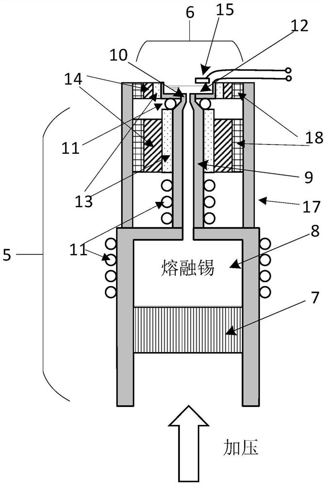
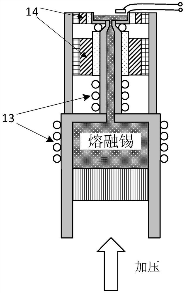
[0037] In the following specific embodiments of the present invention, such as figure 2 As shown, it is a structural schematic diagram of the tin drop generator of the present invention. Compared with the tin drop generator in the prior art, a significant difference is that the overall structure is in an inverted state, that is, the tin drop generat...


PUM


Abstract

The invention discloses a tin drop generating device. The tin drop generating device comprises an inverted tin drop generator body, wherein a tin pool is arranged above a nozzle of the tin drop generator body, and the tin pool is communicated with the nozzle; and a heating coil is arranged on the tin pool and used for heating tin in the tin pool to keep the tin in a molten state. According to thetin drop generating device, the inverted structure design is adopted, the spraying direction of tin drops is changed to be from bottom to top, and a tin pool structure is designed on the nozzle part,so that the nozzle is protected by the molten tin liquid level of a thin layer, and the situation that the spray head is blocked due to tin residues or impurity accumulation is avoided.

Description

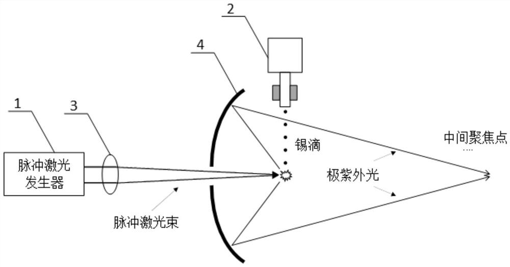
technical field [0001] The invention relates to the technical field of integrated circuit manufacturing lithography equipment, in particular to a tin drop generating device. Background technique [0002] At present, the mainstream extreme ultraviolet (Extremely Ultra-Violet, EUV) lithography machine adopts a laser-produced plasma (Laser Produced Plasma, LPP) light source, and the target material adopts tin (Sn). as attached figure 1 As shown, in the existing photolithography machine, tin is heated to a molten state by the heating device in the tin droplet generator 2, and then sprayed downward drop by drop. The pulsed laser beam emitted by the pulsed laser generator 1 (generally a carbon dioxide gas laser) is focused on the falling tin drop through the focusing lens 3, and heated to a plasma state, thereby generating radiation including 13.5nm extreme ultraviolet light. The ejection frequency of tin droplets is generally 50-200kHz, and the dropping speed of tin droplets is...

Claims


Application Information

Patent Timeline
Patent Type & Authority Applications(China)
IPC IPC(8): G03F7/20B05B1/00B05B15/50
CPCG03F7/70033B05B1/00B05B15/50
Inventor 伍强李艳丽顾峥
Owner SHANGHAI INTEGRATED CIRCUIT EQUIP & MATERIALS IND INNOVATION CENT CO
Learn More