
Design method of helicopter exhaust pipe shaping spoiler

A design method and exhaust pipe technology, applied in design optimization/simulation, special data processing applications, instruments, etc., can solve the problems of tail sieving, tail flow influence of exhaust pipe, and increasing vertical tail aerodynamics, etc. , to achieve the effects of suppressing tail sieving, simple design, and stable wake

Active Publication Date: 2021-03-23
CHINA HELICOPTER RES & DEV INST
View PDF3 Cites 2 Cited by
  • Summary
  • Abstract
  • Description
  • Claims
  • Application Information

AI Technical Summary

Problems solved by technology

[0003] At present, the exhaust pipes of most models of helicopters are installed obliquely upwards at 45° on both sides of the fuselage, and protrude a part of the fuselage. However, this has a significant impact on the wake passing through the exhaust pipes.
However, in a specific downward flight state, the wake flow will act on the vertical tail, resulting in an oscillating lateral force, resulting in tail sifting that is unacceptable to the pilot.
[0004] In response to this problem, a certain type of foreign helicopter installed an airfoil at the rear of the exhaust pipe of the power cabin on the back of the fuselage to at least partially block the airflow flowing from the exhaust port of the power cabin to the tail. The aerodynamic interference wind tunnel test constantly modifies the airfoil of the power cabin, combined with aerodynamic simulation analysis technology, it is found that the installation of the airfoil can move the shedding vortex generated by the exhaust pipe and the main reducer tower to the sides of the fuselage, thereby weakening the airfoil. The adverse effect of the shedding vortex on the vertical tail has stabilized and increased the aerodynamic force of the vertical tail, but it has not completely solved the problem of tail sieving

Method used


Image

  • Design method of helicopter exhaust pipe shaping spoiler
  • Design method of helicopter exhaust pipe shaping spoiler
  • Design method of helicopter exhaust pipe shaping spoiler

Examples


Embodiment 1

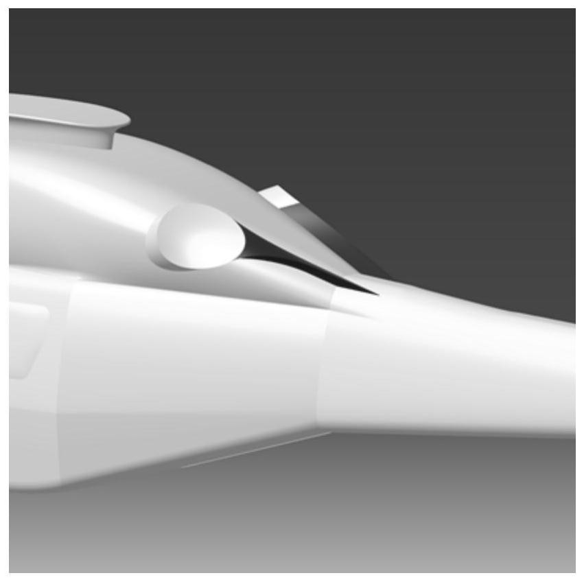
[0052] Using option 1, such as figure 2 As shown, it is a schematic diagram of the position of the exhaust pipe shaping spoiler compared to the fuselage in Scheme 1 of the present invention; the circular arc shape of the leeward surface of the exhaust pipe transitions to the shape of a sheet and connects with the tail beam skin;

[0053] like image 3 As shown, it is a schematic diagram of the shape and key parameters of the exhaust pipe shaping spoiler in Example 1 corresponding to Scheme 1; in Scheme 1, the shaping spoiler is in the shape of a "stretched Y" as a whole, and the specific design process is as follows:

[0054] First, determine the tangential position of the upper and lower surfaces of the spoiler to the annulus of the exhaust pipe and the joint position with the tail beam section, and then determine the contour line, which is consistent with the height of the exhaust pipe protruding from the surface of the body. Shrink towards the middle, and finally transiti...

Embodiment 2

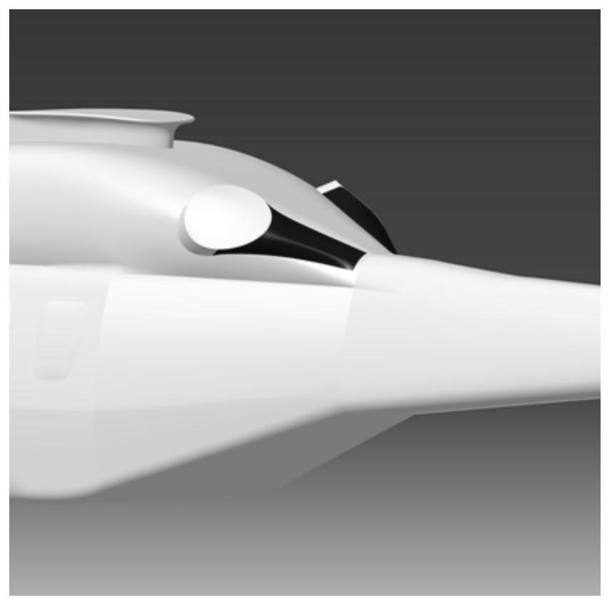
[0057] Using option 2, such as Figure 4 , Figure 5 as shown, Figure 4 It is a schematic diagram of the position of the exhaust pipe shaping spoiler compared to the fuselage in Scheme 2 of the present invention;

[0058] Figure 5 It is a schematic diagram of the shape and key parameters of the exhaust pipe shaping spoiler in Example 2 corresponding to Scheme 2;

[0059] Scheme 2 has a "compressed Y" shape as a whole, and a fairing is added on the leeward side of the exhaust pipe to connect with the fuselage skin; the specific design process is as follows:

[0060] First determine the position tangent to the exhaust pipe annulus and the fuselage surface. In order to obtain a smooth surface with consistent curvature, additional auxiliary lines need to be added. The initial height is consistent with the height of the exhaust pipe, and the height and span of the longitudinal spoiler of the fuselage gradually decrease. , and finally tangent to the fuselage surface, such as ...


PUM


Abstract

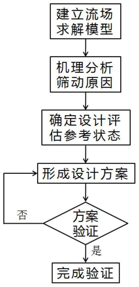
The invention belongs to the technical field of helicopter application, and particularly relates to a design method of a helicopter exhaust pipe shaping spoiler aiming at the problems that in a gliding flight state, when wake flow acts on a vertical fin, the vertical tail pneumatic environment is unstable, oscillating transverse force is generated, and tail screening occurs. The shaping spoiler structure meets the requirement that the leeward area of the exhaust pipe is in smooth transition to the machine body or the leeward face is reduced. The method specifically comprises the following steps: S1, establishing a second-order unsteady display flow field solving model and carrying out gliding state simulation, S2, carrying out mechanism analysis, and determining the reason of tail screening, S3, determining a reference state of design scheme evaluation, S4, forming a design scheme, and S5, carrying out design scheme verification. By means of the design method, the effects of stabilizing wake flow and restraining tail screening can be achieved.

Description

technical field [0001] The invention belongs to the technical field of helicopter applications, and in particular relates to a design method for a helicopter exhaust pipe shaping spoiler. Background technique [0002] As a key part of the power cabin system, the helicopter exhaust pipe is mainly used to mix the high-temperature gas discharged from the engine with the surrounding air, thereby reducing the temperature of the exhaust gas to avoid ablation of the fuselage skin. With the gradual refinement of the technological level and theoretical analysis, the design requirements of the exhaust pipe are also gradually improved. Its shape, layout, and direction have an important impact on the exhaust efficiency, temperature, and noise. Infrared stealth has made targeted modification design research on the exhaust pipe. Since the exhaust of high-temperature gas in the power compartment will be affected by the installation position and the shape of the opening, this is directly r...

Claims


Application Information

Patent Timeline
IPC IPC(8): G06F30/15G06F30/17G06F30/20G06F119/14
CPCG06F30/15G06F30/17G06F30/20G06F2119/14
Inventor 陈笑天吴林波万兵兵孙国普
Owner CHINA HELICOPTER RES & DEV INST
Learn More