Machining method of three-layer clad steel plate

A processing method and layer compounding technology, which is applied in the processing field of three-layer composite steel plate, can solve the problems of affecting the airtightness of the seal, difficult connection, inability to adapt to the high temperature environment of the heating furnace, etc., and achieve the effect of eliminating waste products

Active Publication Date: 2021-03-26
ANHUI BAOHENG ADVANCED MATERIAL TECH CO LTD
View PDF11 Cites 3 Cited by
  • Summary
  • Abstract
  • Description
  • Claims
  • Application Information

AI Technical Summary

Problems solved by technology

However, there are obvious defects in the explosive composite method: 1. It is not suitable for producing thin composite panels with a thickness of less than 10mm; 2. Because it uses the energy of explosives to produce, it will cause vibration, noise and smoke pollution to the environment; and other process conditions, the production efficiency is low
However, the hot-rolled clad plate method also has obvious defects: 1. Large investment and high cost; 2. Due to the limitation of the compression ratio of rolled steel, hot-rolled production cannot produce clad plates with a thickness of more than 50 mm or less than 5 mm.
[0009] In addition, when performing vacuum treatment, it is necessary to open a small hole in the welding seal, and weld a steel pipe at the outer end of the small hole. If the diameter of the small hole is too large, it will directly affect the sealing performance of the seal. If the diameter of the small hole is too small, the vacuum treatment cannot be carried out; and if the outer diameter or wall thickness of the steel pipe is too large, it is difficult to realize the connection with the vacuum equipment, and if the outer diameter or wall thickness of the steel pipe is too small, it cannot adapt to heating. In the high temperature environment above 1000℃ in the furnace, it is easy to be burned through

Method used


Image

  • Machining method of three-layer clad steel plate

Examples


Embodiment 1

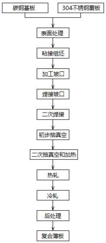
[0039] see figure 1 , one substrate is made of carbon steel plate, and the two cladding plates are made of stainless steel plate. The specific processing steps are as follows:

[0040] S1. Surface treatment: Surface treatment is carried out on the surface to be bonded of the substrate and the surface to be bonded of the cover plate, that is, the two sides of the substrate and one side of the cover plate respectively, and the surface to be bonded of the substrate and the surface to be bonded of the cover plate are removed. Sticky sand and scale.

[0041] Specifically, the substrate is sent into the shot blasting machine, and the shot blasting device of the shot blasting machine throws projectiles (steel balls) at high speed, impacts the two sides of the substrate respectively, and removes the sticky sand and scale on both sides until the surface is clean and free of rust. ; Send the cladding plate into the shot blasting machine, and the shot blaster of the shot blasting machin...

Embodiment 2

[0056] see figure 1 , one substrate is made of carbon steel plate, and the two cladding plates are made of stainless steel plate. The specific processing steps are as follows:

[0057] S1. Surface treatment: Surface treatment is carried out on the surface to be bonded of the substrate and the surface to be bonded of the cover plate, that is, the two sides of the substrate and one side of the cover plate respectively, and the surface to be bonded of the substrate and the surface to be bonded of the cover plate are removed. Sticky sand and scale.

[0058] Specifically, the substrate is sent into the shot blasting machine, and the shot blasting device of the shot blasting machine throws projectiles (steel balls) at high speed, impacts the two sides of the substrate respectively, and removes the sticky sand and scale on both sides until the surface is clean and free of rust. ; Send the cladding plate into the shot blasting machine, and the shot blaster of the shot blasting machin...

Embodiment 3

[0073] see figure 1 , one substrate is made of carbon steel plate, and the two cladding plates are made of stainless steel plate. The specific processing steps are as follows:

[0074] S1. Surface treatment: Surface treatment is carried out on the surface to be bonded of the substrate and the surface to be bonded of the cover plate, that is, the two sides of the substrate and one side of the cover plate respectively, and the surface to be bonded of the substrate and the surface to be bonded of the cover plate are removed. Sticky sand and scale.

[0075] Specifically, the substrate is sent into the shot blasting machine, and the shot blasting device of the shot blasting machine throws projectiles (steel balls) at high speed, impacts the two sides of the substrate respectively, and removes the sticky sand and scale on both sides until the surface is clean and free of rust. ; Send the cladding plate into the shot blasting machine, and the shot blaster of the shot blasting machine ...


PUM

PropertyMeasurementUnit
thicknessaaaaaaaaaa
thicknessaaaaaaaaaa
thicknessaaaaaaaaaa

Abstract

The invention discloses a machining method of a three-layer clad steel plate. The machining method comprises the following steps: (1) surface treatment; (2) assembling; (3) groove machining; (4) segmental pressure application, groove welding and complete welding and sealing; (5) primary vacuumizing treatment; (6) secondary vacuumizing treatment and heating; (7) hot rolling; (8) cold rolling; (9) post-treatment to obtain a composite sheet. According to the machining method, an adhesive is adopted for bonding in the assembling process, so that primary connection is achieved; the grooves are machined in the welding process, pressure is applied in a segmented mode, and welding and secondary welding are conducted on the grooves, so that a combined blank plate is prevented from locally protruding or tilting; a two-time vacuumizing treatment mode and a heating mode are adopted during vacuumizing, so that firm metallurgical bonding can be formed between a base plate and a covering plate; and the carbon steel and stainless steel double-sided composite sheet machined by the machining steps has corrosion resistance, high mechanical strength and machinability.

Description

technical field [0001] The invention relates to the technical field of production of stainless steel clad plates, in particular to a processing method of a three-layer clad steel plate. Background technique [0002] The stainless steel clad plate is a clad steel plate made of a carbon steel substrate and a stainless steel cladding plate or different series of stainless steel substrates and cladding plates. Its main feature is that carbon steel and stainless steel form a strong metallurgical bond, which can be processed by hot pressing, cold bending, cutting, welding, etc., and has good process performance. [0003] At present, there are three main methods for industrial production of stainless steel clad plate industry, namely explosive clad method, hot rolling clad method and cold rolled clad method. [0004] The explosive composite method is to place the cladding plate on the base plate overlappingly, and a certain distance is set between the cladding plate and the base p...

Claims


Application Information

Patent Timeline
Patent Type & Authority Applications(China)
IPC IPC(8): B23P15/00
CPCB23P15/00
Inventor 洪功正
Owner ANHUI BAOHENG ADVANCED MATERIAL TECH CO LTD
Why Eureka
Try Eureka