

Chipping separation device of machining grinding machine
A separation device and grinding machine technology, which is applied in the direction of grinding/polishing safety devices, metal processing equipment, manufacturing tools, etc., can solve the problems that iron filings and grinding stone particles cannot be discharged in time, increase the difficulty of filtration, and cannot be realized, and achieve increased Filtration difficulty, improvement of water recycling effect, and improvement of utilization rate
- Summary
- Abstract
- Description
- Claims
- Application Information
AI Technical Summary
Problems solved by technology
Method used
Image

Examples
Embodiment 1
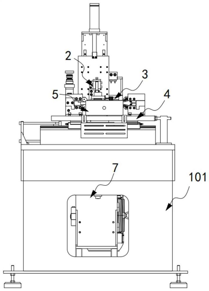
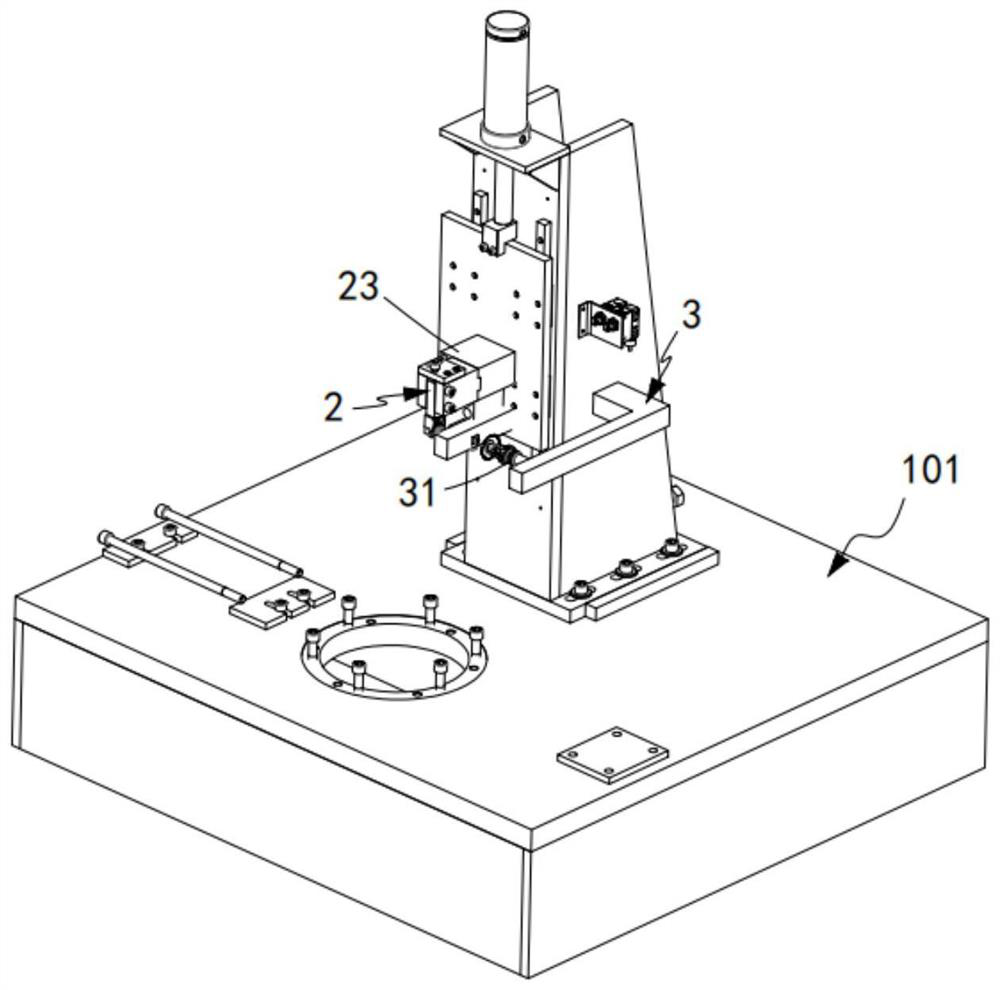
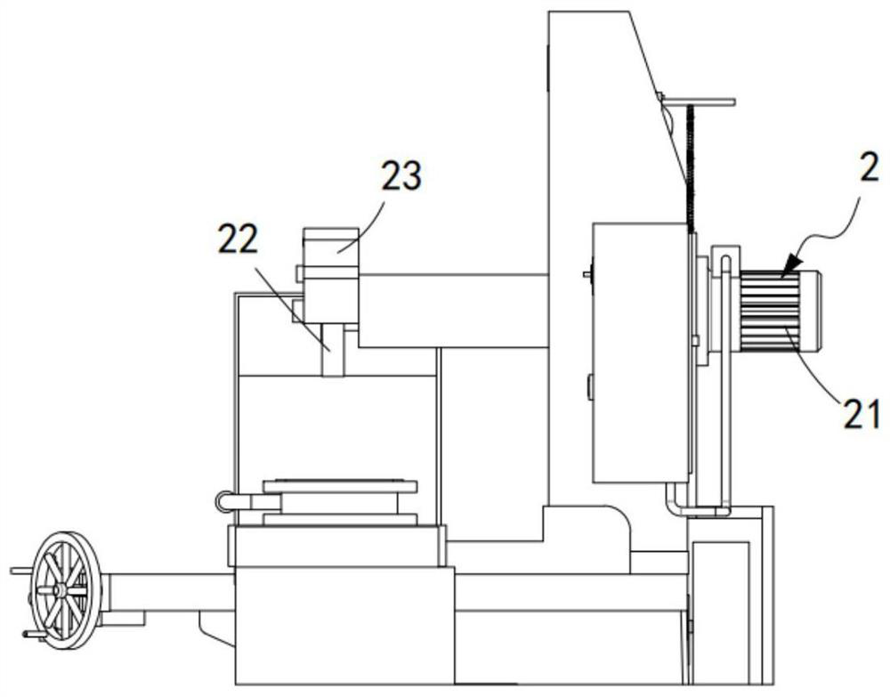
[0063] Such as figure 1 As shown, a grinding machine chip separation device includes a grinding machine 101, a grinding mechanism 2 installed on the grinding machine 101, a cooling mechanism 3 arranged on one side of the grinding mechanism 2, and a cooling mechanism 3 arranged under the grinding mechanism 2. And the carrying mechanism 4 installed on the grinding machine 101, two sets of impurity removal mechanisms 5 arranged symmetrically on both sides of the carrying mechanism 4 and used to collect impurities on the carrying mechanism 4, arranged on the An iron filings filter mechanism 6 arranged under the impurity removal mechanism 5 and communicated with the impurity removal mechanism 5 , and a grindstone particle filter mechanism 7 arranged under the iron filings filter mechanism 6 and communicated with the cooling mechanism 3 at the other end;
[0064] The impurity removal mechanism 5 works synchronously with the grinding mechanism 2 through the first transmission mechani...
Embodiment 2
[0127] Such as Figure 13 to Figure 15 As shown, the components that are the same as or corresponding to those in the first embodiment are marked with the corresponding reference numerals in the first embodiment. For the sake of simplicity, only the differences from the first embodiment will be described below. The difference between this embodiment two and embodiment one is:
[0128] further, such as Figure 13 to Figure 15 As shown, the iron filings collection assembly 62 includes a first filter plate 621 fixedly arranged on the frame 41 and matched with the inner wall of the frame 41, a hole and a hole opened on the frame 41 that are slidably arranged on the frame 41 and The holes of the first filter plate 621 are staggered and the second filter plate 622 is arranged alternately, two sets of connecting rods 624 are set in the guide rails 623 on the frame 41 through sliding blocks, and the connecting rods 624 are fixedly arranged on the connecting rods 623 . The stopper 62...
PUM
 Abstract
Description
Claims
Application Information