Parallel radial magneto-rheological valve and damper

A magneto-rheological valve, parallel technology, applied in the direction of shock absorber, shock absorber, spring/shock absorber, etc., can solve the problem of the reduction of the buffering efficiency of the magnetorheological damper, the small dynamic range of the magnetorheological damper, Problems such as impact load cannot be effectively alleviated to achieve the effect of improving controllability, increasing the range of damping force and dynamic range, and protecting life safety and equipment safety

Active Publication Date: 2021-03-26
CHONGQING UNIV
View PDF10 Cites 3 Cited by
  • Summary
  • Abstract
  • Description
  • Claims
  • Application Information

AI Technical Summary

Problems solved by technology

In a low-speed environment, the vibration isolation system does not have high requirements on the damping force performance of the damper. The traditional magnetorheological damper can provide reasonable performance for the semi-active control system, but the dynamic range of the traditional magnetorheological damper varies with As the piston speed increases, it decreases significantly, so the impact load cannot be effectively reduced in a high-speed environment, and the buffering efficiency of the magneto-r

Method used


Image

  • Parallel radial magneto-rheological valve and damper
  • Parallel radial magneto-rheological valve and damper
  • Parallel radial magneto-rheological valve and damper

Examples


Embodiment Construction

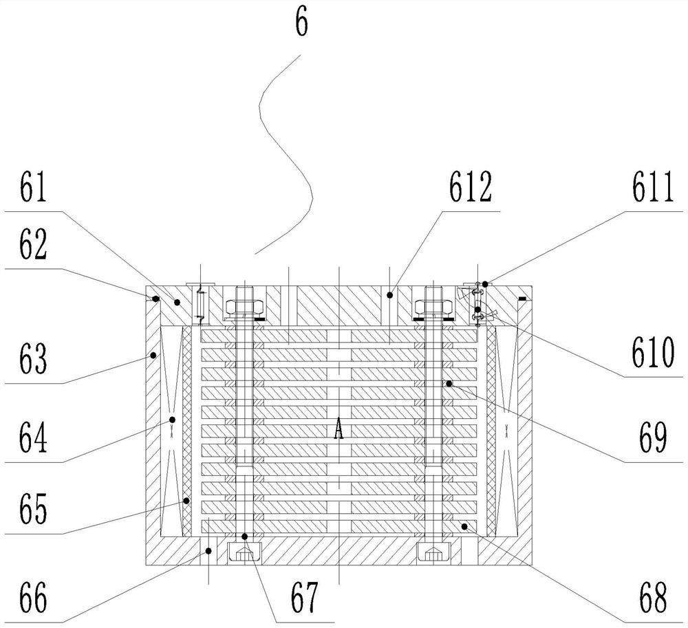
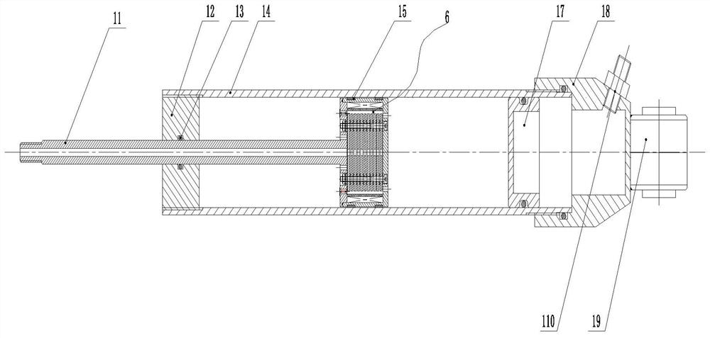
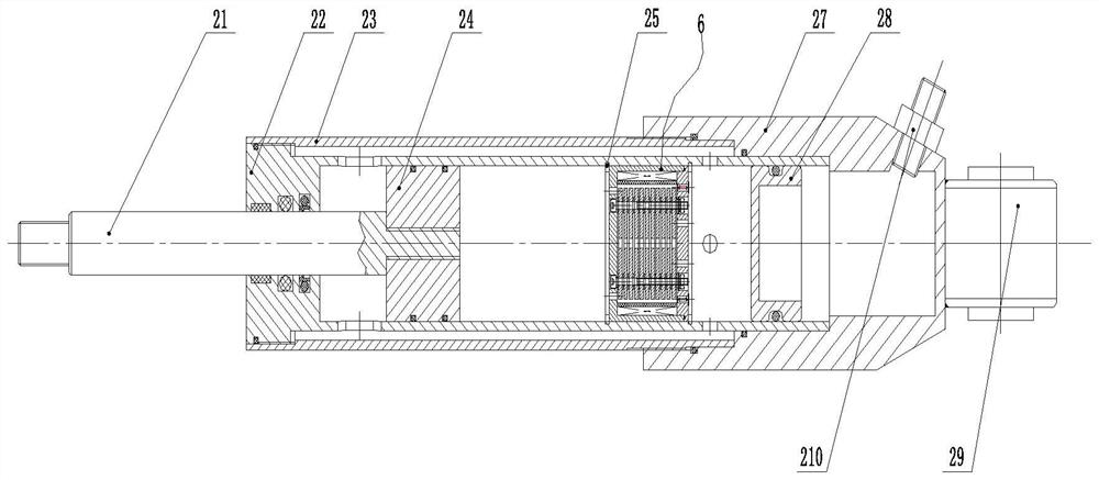
[0021] figure 1 It is a structural schematic diagram of a parallel radial magneto-rheological valve of the present invention; figure 2 It is a structural schematic diagram of the first shock absorber of the present invention; image 3 It is a structural schematic diagram of the second shock absorber of the present invention; Figure 4 It is a structural schematic diagram of the third shock absorber of the present invention; as shown in the figure, a parallel radial magneto-rheological valve 6 includes a piston outer cylinder 63 and a piston upper end cover 61 arranged at the end of the piston outer cylinder 63, and the upper end cover A sealing ring 62 is also provided between 61 and the piston outer cylinder 63, and an O-shaped sealing ring 62 is used to ensure a good internal sealing effect; the piston outer cylinder 63 is evenly spaced with a plurality of magnetic plates 68 along the axial direction, so A coil spacer 65 is arranged between the magnetically conductive she...


PUM


Abstract

The invention discloses a parallel radial magneto-rheological valve which comprises a piston outer cylinder and a piston upper end cover arranged at the end of the piston outer cylinder; a plurality of magnetic conductive sheets are evenly arranged on the piston outer cylinder at intervals in the axial direction, and coil separation cylinders are arranged between the magnetic conductive sheets andthe piston outer cylinder; magnet exciting coils are arranged between the coil separation cylinders and the piston outer cylinder; and magnetic conductive sheet holes are formed in the centers of themagnetic conductive sheets in the axial direction, the magnetic conductive sheet holes are through in the axial direction to form first flow guide channels, gaps among the multiple magnetic conductive sheets form second flow guide channels in the radial direction, and third flow guide channels are formed between the magnetic conductive sheets and the coil separation cylinders. According to the parallel radial magneto-rheological valve, the flow guide channels in the radial direction are combined with a multi-channel parallel structure, and meanwhile, controllable coulomb damping force is increased and uncontrollable viscous damping force is reduced, so that the dynamic range of a magneto-rheological damper is greatly enlarged, the controllability of the magneto-rheological damper is greatly improved, and the buffer performance of the magneto-rheological damper in a high-speed impact environment is improved.

Description

technical field [0001] The invention relates to the field of magnetorheological damping, in particular to a parallel radial magnetorheological valve and a damper thereof. Background technique [0002] Cushioning refers to the process of alleviating the mechanical vibration of equipment such as vehicles, helicopters and heavy weapons when they are subjected to high-speed impact, so that the force is flattened. In practice, these impact situations will cause the occupants and mechanical equipment to be greatly impacted, thereby endangering the life safety of the occupants and the safety of equipment, so it is necessary to take buffer measures. The magnetorheological buffer device is a semi-active buffer device developed with the magnetorheological medium as the filling material, which can change the rheological characteristics in milliseconds with the help of the magnetorheological medium under the action of a magnetic field. The performance of the semi-active buffer system m...

Claims


Application Information

Patent Timeline
IPC IPC(8): F16F9/53F16F9/34F16F9/348F16F9/36
CPCF16F9/537F16F9/348F16F9/3405F16F9/369
Inventor 董小闵王陶石开元
Owner CHONGQING UNIV
Why Eureka
Try Eureka