
A preparation method of a saturable absorber and a multimode fiber laser

A saturable absorption, multimode fiber technology, applied in the field of laser technology and nonlinear optics, can solve the problem of low output pulse energy, and achieve the effect of high saturation power and high modulation depth

Active Publication Date: 2022-04-26
SOUTH CHINA NORMAL UNIVERSITY
View PDF8 Cites 0 Cited by
  • Summary
  • Abstract
  • Description
  • Claims
  • Application Information

AI Technical Summary

Problems solved by technology

[0003] In view of this, in order to solve the problem of low output pulse energy of current single-mode fiber lasers and multi-mode fiber lasers, the present invention proposes a preparation method of a saturable absorber and a multi-mode fiber laser to achieve high-energy pulse laser output

Method used


Image

  • A preparation method of a saturable absorber and a multimode fiber laser
  • A preparation method of a saturable absorber and a multimode fiber laser
  • A preparation method of a saturable absorber and a multimode fiber laser

Examples


Embodiment 1

[0028] The invention provides a graphene-coated multi-mode micro-nano optical fiber saturable absorber, comprising: a multi-mode micro-nano optical fiber and a graphene deposition layer deposited thereon by an optical deposition method.

Embodiment 2

[0030] The preparation method of the graphene-coated multimode micro-nano optical fiber saturable absorber of the present invention comprises the following steps:

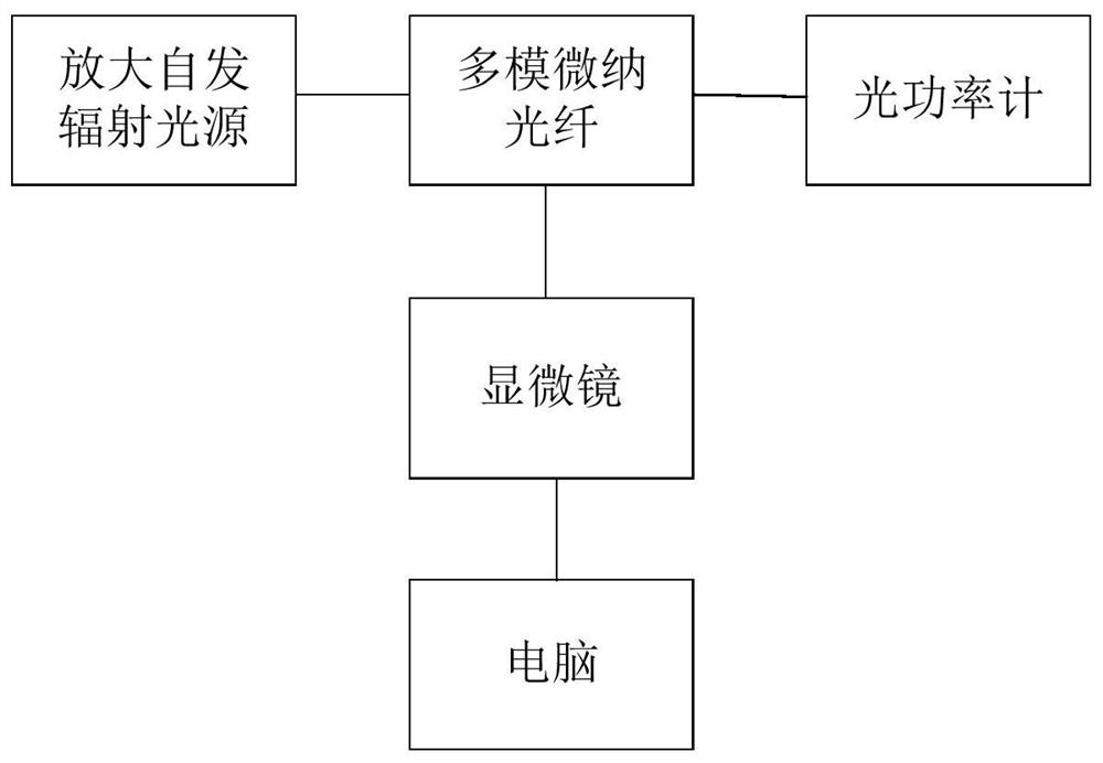
[0031] (1) Peel off the coating layer of an ordinary graded-index multimode fiber with a core diameter of 50 microns or 62.5 microns and wipe it clean with alcohol, then heat it on an alcohol lamp to taper it to Multimode micro-nano fiber with a diameter of 4-20 microns. Among them, the input end of the multimode micro-nano fiber is connected to the amplified spontaneous emission light source, the output end is connected to the optical power meter, and the amplified spontaneous emission light source is turned on during the tapering process to monitor the loss in the tapering process in real time through the power meter, so that the loss lower than 3dB;

[0032] (2) Keep the connection between the amplified spontaneous emission light source and the optical power meter and the multimode micro-nano fiber, and fix the...

Embodiment 3

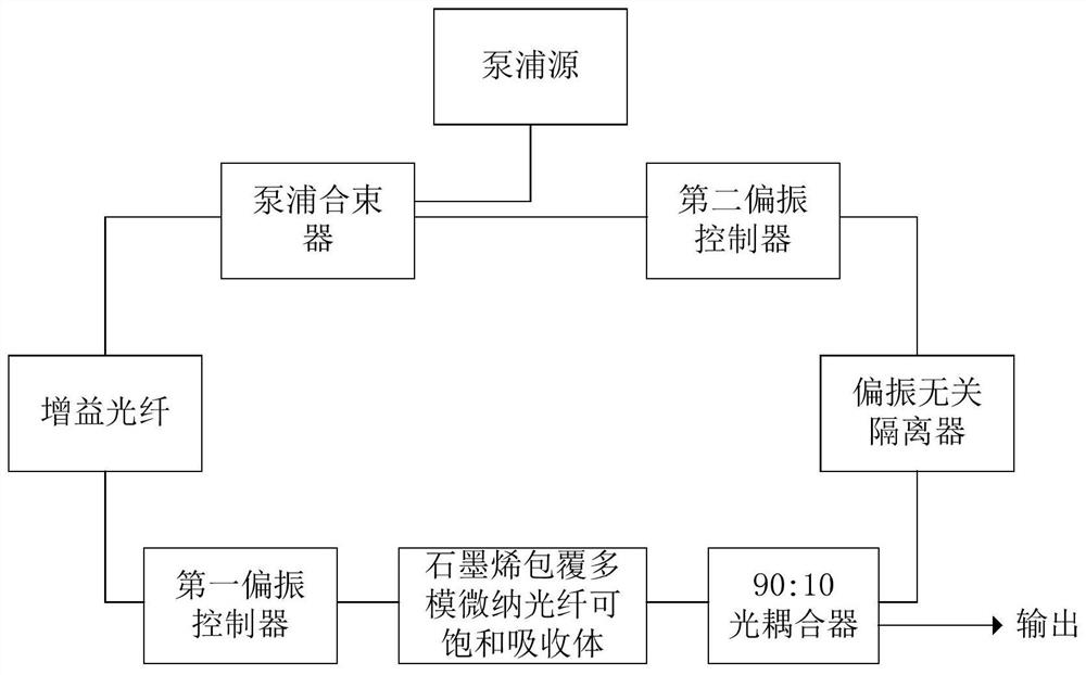
[0035] The all-fiber structure high-energy Q-switched mode-locked multimode fiber laser of the present invention is a ring cavity structure, such as image 3 As shown, by sequentially connecting pump beam combiner, gain fiber, first polarization controller, graphene-coated multimode micro-nano fiber saturable absorber, 90:10 optical coupler, polarization-independent isolator, second polarization The controller and the pump combiner form an annular chamber. The pump source is connected to the resonant cavity through the other end of the pump beam combiner, and the 10% port of the optical coupler is used as the output of the laser cavity to monitor the output characteristics of the laser cavity.

[0036] In this embodiment, the gain fiber is an ytterbium-doped few-mode fiber with a core diameter of 10 microns and a cladding diameter of 125 microns. The two pigtails connected to the pump beam combiner, the gain fiber and the second polarization controller are both few-mode fiber...


PUM

PropertyMeasurementUnit
diameteraaaaaaaaaa
concentrationaaaaaaaaaa
diameteraaaaaaaaaa

Abstract

The invention discloses a preparation method of a saturable absorber and a multimode fiber laser. Ordinary multimode fiber is tapered into micro-nano fiber by fusion tapering method, and then graphene is deposited on the surface of multimode micro-nano fiber by optical deposition method, so as to prepare graphene-coated multimode micro-nano fiber which can be saturable Absorber; at the same time, an all-fiber structure multimode fiber laser based on the saturable absorber is provided, which realizes a high-energy Q-switched mode-locked pulse output with a pulse energy of 311.0nJ; the multimode fiber laser of the present invention has an all-fiber structure , high output pulse energy and small volume, while the graphene-coated multimode micro-nano fiber used in the laser cavity has the advantages of high saturation power, high modulation depth, simple fabrication and low cost.

Description

technical field [0001] The invention relates to the fields of laser technology and nonlinear optics technology, in particular to a preparation method of a saturable absorber and a multimode fiber laser. Background technique [0002] High-energy fiber lasers have attracted much attention due to their wide range of applications in remote sensing, ranging, medical and laser processing. Q-switching and mode-locking are two main methods of generating pulsed lasers, while Q-switching mode-locking is in the middle state between the two. Its remarkable feature is that its pulse sequence is periodically Q-switched by the mode-locked pulse sequence. Pulse train modulation. Compared with the mode-locked pulse, the Q-switched mode-locked pulse has the advantages of high energy and adjustable repetition frequency. At present, most Q-switched mode-locked pulses are generated by passive modulation techniques including various saturable absorbers. As one of the saturable absorbers, graph...

Claims


Application Information

Patent Timeline
Patent Type & Authority Patents(China)
IPC IPC(8): H01S3/11H01S3/067
CPCH01S3/1115H01S3/06708H01S3/06791
Inventor 罗爱平吴家文罗智超林旭斌徐文成
Owner SOUTH CHINA NORMAL UNIVERSITY
Learn More