3D printing method and device based on pulse current

A pulse current and 3D printing technology, which is applied in 3D printing and space manufacturing, can solve the problems of easy crystallization of amorphous alloy materials, achieve the effect of increasing the transition temperature, small discharge area, and avoiding crystallization behavior

Active Publication Date: 2021-04-02
CHINA ACADEMY OF SPACE TECHNOLOGY
View PDF7 Cites 5 Cited by
  • Summary
  • Abstract
  • Description
  • Claims
  • Application Information

AI Technical Summary

Problems solved by technology

[0011] To this end, the present invention provides a 3D printing method and device based on electric pulses, which not only solves the problem of easy crystallization of amorphous alloy materials, but also realizes the diversity of shaped amorphous alloy samples, and proposes new methods for space manufacturing of metal materials. train of thought

Method used


Image

  • 3D printing method and device based on pulse current
  • 3D printing method and device based on pulse current
  • 3D printing method and device based on pulse current

Examples


Embodiment 1

[0048] This embodiment realizes the welding between Fe base, La and Zr base amorphous alloy strips and keeps its amorphous characteristics by pulse current, see Figure 4 , showing fabrication drawings of welds between Fe-based, La and Zr-based amorphous alloy strips, see Figure 5 , shows the XRD results before and after welding between Fe-based, La and Zr-based amorphous alloy strips, proving that the welded product still maintains an amorphous structure; the specific steps are as follows:

[0049] 1. Selection of parameters

[0050] Fe-based amorphous alloy strip: choose 4700μF capacitor, discharge current 200A, current pulse width 0.5ms, welding point spacing 0.5mm, pressure value 3.5kg as the diffusion bonding control conditions of amorphous alloy strip.

[0051] La-based amorphous alloy strip: choose 4700μF capacitor, discharge current 400A, current pulse width 1ms, welding point spacing 0.5mm, pressure value 4kg as the diffusion bonding control conditions of amorphous ...

Embodiment 2

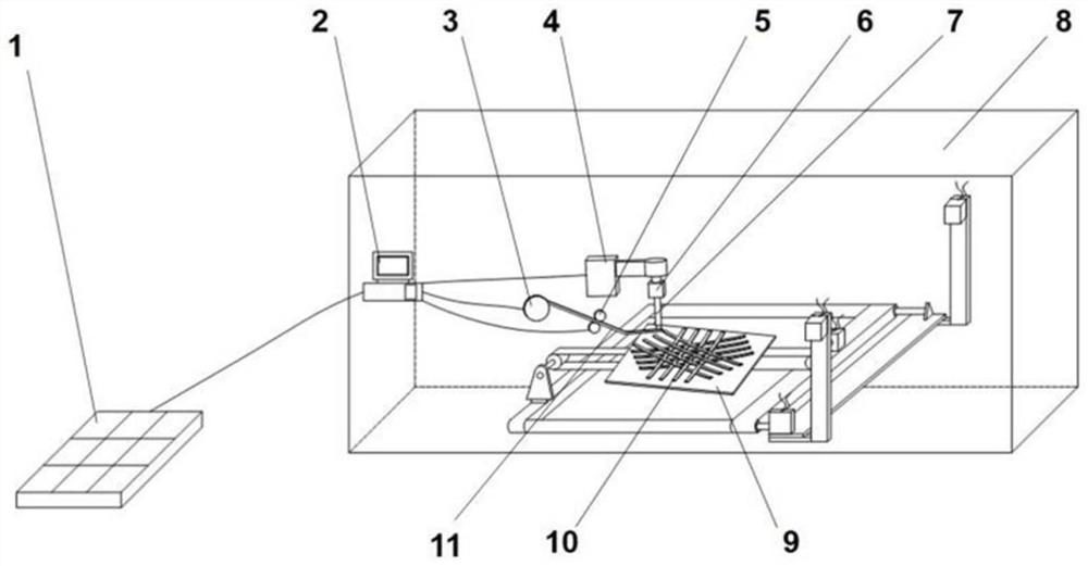
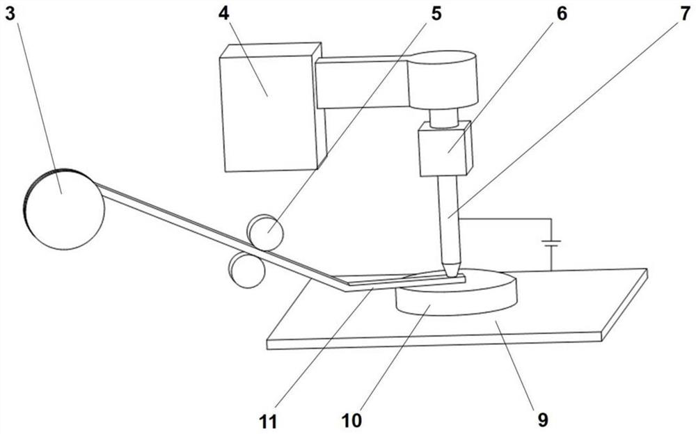
[0061] This embodiment is a 3D printing device based on pulse current, see figure 2 and image 3 As shown, it includes a frame 8, which is composed of aluminum alloy installation, and also includes a forming device and a control device 2 arranged in the frame 8. The control device 2 is connected to the forming device, and the control device is connected through a data line / wireless communication device. Send instructions to the forming device for real-time control. Among them, the forming device includes a transmission device 4, a metal electrode 7, a pulley 3, and a transmission wheel 5. The metal electrode 7 is connected to the transmission device 4 in transmission, and is driven by the transmission device 4 to perform linear reciprocating motion up and down; the pulley 3 is equipped with an amorphous Alloy material, transmission wheel 5 is arranged between belt pulley 3 and metal electrode 7, is used for the amorphous alloy material in belt pulley 3 is conveyed below meta...


PUM

PropertyMeasurementUnit
electrical resistivityaaaaaaaaaa

Abstract

The invention provides a 3D printing method based on pulse current. The method comprises the following steps of using an amorphous alloy wire or a strip as a raw material, carrying out spot pressing on the amorphous alloy wire or the strip, welding by the pulse current, and stacking layer by layer to form a three-dimensional sample piece. According to the method, the pulse current is used as a heat source for amorphous alloy space additive manufacturing, on one hand, power consumption needed in the manufacturing process is far smaller than that of electron beams, lasers and other traditional heat sources, the energy utilization rate is increased, low-power-consumption additive manufacturing is achieved, on the other hand, the pulse current is used for rapid heating, so that an amorphous alloy is in a non-molten state with low viscosity, the problems that a molten pool is difficult to control under microgravity and heat dissipation and solidification are difficult and the like in a high-vacuum environment in a traditional 3D printing method of metal materials can be solved, and the stability of the space additive manufacturing process can be improved. Besides, point pressure rapid welding and layer-by-layer additive manufacturing are conducted on the amorphous alloy through the pulse current, the thermal action time in the additive manufacturing process is accurate and controllable, the amorphous structure of the raw materials can be kept, and the mechanical property of an additive sample piece is improved.

Description

technical field [0001] The invention belongs to the technical field of 3D printing, is applicable to the space manufacturing field, and specifically relates to a 3D printing method and device based on electric pulses. Background technique [0002] In-space Additive Manufacturing (In-space Additive Manufacturing) for the space environment, that is, "manufactured in space and served in space", can break through the strict restrictions on the volume, weight and structural strength of the launch vehicle during launch, and realize different sizes , On-orbit manufacturing of spacecraft structures with complex shapes, improving the flexibility of space mission execution. At the same time, in the microgravity environment of space, the spacecraft structure and strength design can be simplified, and "small equipment" can be used to manufacture "big structures". Therefore, the development of space additive manufacturing technology is a strategic requirement for all countries to seize ...

Claims


Application Information

Patent Timeline
Patent Type & Authority Applications(China)
IPC IPC(8): B29C64/118B29C64/393B29C64/20B33Y10/00B33Y30/00B33Y50/02
CPCB29C64/118B29C64/393B29C64/20B33Y10/00B33Y30/00B33Y50/02
Inventor 赵少凡张琪廖超群白海洋刘明董雯焦志伟汪卫华
Owner CHINA ACADEMY OF SPACE TECHNOLOGY
Why Eureka
Try Eureka