Carbon fiber composite material front-end reinforcing beam and preparation method thereof

A composite material and reinforcing beam technology, which is applied in the field of auto parts to achieve the effects of excellent rigidity, excellent comprehensive performance and high porosity

Active Publication Date: 2021-04-06
JIANGSU HENGRUI CARBON FIBER TECH CO LTD
View PDF17 Cites 0 Cited by
  • Summary
  • Abstract
  • Description
  • Claims
  • Application Information

AI Technical Summary

Problems solved by technology

[0005] The technical problem mainly solved by the present invention is to provide a carbon fiber composite material front-end reinforcement beam and its preparation method, which can solve the above-mentioned problems existing in the existing automobile front-end reinforcement beam

Method used


Image

  • Carbon fiber composite material front-end reinforcing beam and preparation method thereof
  • Carbon fiber composite material front-end reinforcing beam and preparation method thereof
  • Carbon fiber composite material front-end reinforcing beam and preparation method thereof

Examples


Embodiment 1

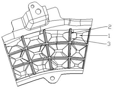
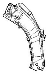
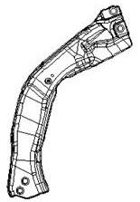
[0028] The present invention discloses a carbon fiber composite material front reinforced beam, which has a left front reinforced beam and a right front reinforced beam, including a reinforced beam body 1 and a rib 2; the reinforced beam body 1 is designed as a bow with a bending radius of 8-12mm type structure, the thickness of the reinforcing beam body 1 is 3 mm, and the flange height of its edge is 16-24 mm; the reinforcing ribs 2 are distributed on the back of the reinforcing beam body 1 in a grid pattern; There is also a reinforcement layer 3 with variable wall thickness around; the thickness of the reinforcement layer 3 gradually decreases from the side of the reinforcement 2 to the side of the reinforcement beam body 1; the reinforcement beam body 1, reinforcement 2 It is integrally formed with the reinforcing layer 3. Through the structural design of the reinforcement beam body 1, the design of the reinforcement rib 2 and the reinforcement layer 3, the overall rigidity...

Embodiment 2

[0033] A method for preparing a front-end reinforced beam of a carbon fiber composite material. The raw material of the carbon fiber SMC sheet is an epoxy vinyl resin system, the mass percentage of the fiber is 53%, and the length of the carbon fiber is 25-26 mm.

[0034] The forming mold selected is a metal mold with one mold and two cavities. The mold temperature is controlled at 135°C by an oil temperature controller.

[0035] The thickness of the front reinforcing beam body 1 is designed to be 3 mm, the thickness of the reinforcing layer 3 from the end point on the side near the reinforcing rib 2 to the opposite side of the reinforcing beam body 1 is 4 mm; the thickness of the reinforcing rib 2 is 3 mm.

[0036] Described preparation method specifically comprises the following steps:

[0037] (1) Raw material punching and layering: place the carbon fiber SMC sheet on the punch platform, and form the reinforcing beam body into a sheet of the required shape and size at the ...

Embodiment 3

[0045] A method for preparing a front reinforced beam of carbon fiber composite material. The raw material carbon fiber SMC sheet is an epoxy resin system, the mass percentage of the fiber is 50-52%, and the length of the carbon fiber is 25-26mm.

[0046] The forming mold selected is a metal mold with one mold and two cavities. The mold temperature is controlled at 145°C by an oil temperature controller.

[0047] The thickness of the front reinforcing beam body 1 is designed to be 3 mm, the thickness of the reinforcing layer 3 from the end point on the side near the reinforcing rib 2 to the opposite side of the reinforcing beam body 1 is 4 mm; the thickness of the reinforcing rib 2 is 3 mm.

[0048] Described preparation method specifically comprises the following steps:

[0049] (1) Raw material punching and layering: place the carbon fiber SMC sheet on the punch platform, and form the reinforcing beam body into a sheet of the required shape and size at the punching place of...


PUM

PropertyMeasurementUnit
thicknessaaaaaaaaaa
angleaaaaaaaaaa
radiusaaaaaaaaaa

Abstract

The invention discloses a carbon fiber composite material front-end reinforcing beam and a preparation method thereof; the carbon fiber composite material front-end reinforcing beam comprises a front-end reinforcing beam body and reinforcing ribs, and the front-end reinforcing ribs are located on the back surface of the reinforcing beam body; reinforcing layers are arranged on the peripheries of the reinforcing ribs. The thickness of the reinforcing layer is linearly reduced from one side of the reinforcing rib to the surface of the reinforcing beam body at the front end; the preparation method comprises the following steps: (1), performing raw material punching and layering; (2), performing pre-vacuumizing; (3), putting the product into a mold; and (4), performing SMC forming. The carbon fiber SMC sheet is adopted, and through the design of the variable-thickness reinforcing layer structure, the design of the reinforcing beam body of the bow-shaped structure, the pre-vacuumizing treatment and the design of the mold entering angle of the laminated sheet, the problems that reinforcing ribs of a finished reinforcing beam at the front end of the carbon fiber composite material shrink and the porosity is high are effectively solved; the surface of the obtained formed product has a bright forged carbon pattern effect, is high in apparent mass, has excellent rigidity, mechanical property, first-order inherent frequency and deformation resistance, and is excellent in comprehensive performance.

Description

technical field [0001] The invention relates to the field of auto parts, in particular to a carbon fiber composite material front reinforcement beam and a preparation method thereof. Background technique [0002] Traditional fuel vehicles have increasingly urgent requirements for fuel consumption regulations and new energy vehicles for cruising range, and vehicle lightweight has become an urgent demand for domestic automobile OEMs. The lightweight of the car can reduce the quality of the vehicle, improve fuel efficiency, increase the cruising range, and thus reduce the cost of using the car. [0003] The reinforcement beam at the front end of the car is one of the important parts of the side structure of the engine compartment, and it is one of the force transmission paths of the frontal collision. Traditional automobile front-end reinforcement beams are generally made of steel through stamping and welding processes. The products are not only heavy, but also require many as...

Claims


Application Information

Patent Timeline
Patent Type & Authority Applications(China)
IPC IPC(8): B60R19/02B60R19/03B29C70/18B29C70/34B29C70/44
CPCB60R19/023B60R19/03B29C70/18B29C70/342B29C70/44
Inventor 顾勇涛张盛祝艳来王成刘本
Owner JIANGSU HENGRUI CARBON FIBER TECH CO LTD
Why Eureka
Try Eureka