Coiled tubing plate-plate butt welding equipment and welding method

A welding equipment and welding method technology, applied in welding equipment, plasma welding equipment, welding/welding/cutting items, etc., can solve the problems of beveling of steel strips, difficult to original steel strips, limited welding thickness, etc.

Pending Publication Date: 2021-04-09
XINDA KECHUANG TANGSHAN PETROLEUM EQUIP CO LTD
View PDF0 Cites 1 Cited by
  • Summary
  • Abstract
  • Description
  • Claims
  • Application Information

AI Technical Summary

Problems solved by technology

At present, the existing steel strip butt joint machine mainly adopts argon arc welding, and its welding thickness is limited. At the same time, the steel strip needs to be beveled. The thickness and wide band of the welded steel strip are difficult to match the original steel strip due to the problem of welding burn. unanimous

Method used


Image

  • Coiled tubing plate-plate butt welding equipment and welding method

Examples


Embodiment 1

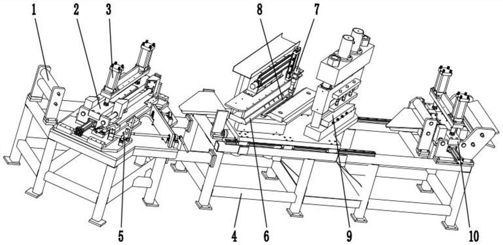
[0025] like figure 1 As shown, a coiled tubing plate-to-plate butt welding equipment includes a bracket 4 and a steel strip straightening wheel 1, a steel strip position adjustment device 2, and a steel strip welding clamping device that are sequentially arranged on the support 4 from left to right 6. Plasma torch 7, steel strip cutting device 9 and steel strip clamping device 10, said steel strip position adjusting device 2 is provided with adjusting steel strip position knob 5 and air pressure driving device 3, said adjusting steel strip position knob 5 The position of the steel belt can be adjusted, and the pneumatic driving device 3 can push and compress the steel belt after being pressurized.

[0026] When the coiled tubing plate-to-plate butt welding equipment and welding method of the present embodiment 1 are in use, first a steel strip is put into the steel strip cutting device 9 through the steel strip clamping device 10, and the steel strip is paired by the steel str...

Embodiment 2

[0038] A coiled tubing plate butt welding method, comprising the following steps:

[0039] Step 1, first put a steel strip into the steel strip cutting device 9 through the steel strip clamping device 10, and fix the steel strip through the steel strip clamping device 10, and send the steel strip cut by the steel strip cutting device 9 into The bottom of the steel strip welding clamping device 6, and then another steel strip is put into the steel strip position adjustment device 2 through the steel strip straightening wheel 1, and then sent to the bottom of the steel strip welding clamping device 6. At this time, the steel strip can be adjusted The position knob 5 adjusts the position of the steel belt, and after the position adjustment is completed, the steel belt is pressed by the pneumatic drive device 3 to fix it;

[0040] Step 2: Arrange the arc starting plate and the arc extinguishing plate at both ends of the steel strip, and press and fix the ends of the two steel stri...


PUM


Abstract

The invention discloses a coiled tubing plate-plate butt welding equipment and welding method. The coiled tubing plate-plate butt welding equipment comprises a support, a steel belt straightening wheel, a steel belt position adjusting device, a steel belt welding and clamping device, a plasma welding gun, a steel belt cutting device and a steel belt clamping device, wherein the steel belt straightening wheel, the steel belt position adjusting device, the steel belt welding and clamping device, the plasma welding gun, the steel belt cutting device and the steel belt clamping device are sequentially arranged on the support from left to right. The steel belt position adjusting device is provided with a steel belt position adjusting knob and an air pressure driving device, the steel belt position adjusting knob can adjust the position of a steel belt, and the air pressure driving device can push and press the steel belt after pressurization. According to the coiled tubing plate-plate butt welding equipment and welding method, the welding quality can be guaranteed, through plasma welding, a thermal induction area is smaller, the welding thickness range is wider, beveling is not needed in welding, the welding automation degree is high, and welding is more standardized.

Description

technical field [0001] The invention relates to the technical field of oil and gas pipes, in particular to a plate-to-plate butt welding equipment and a welding method of a continuous oil tube. Background technique [0002] Coiled tubing is a special steel pipe used in oil and gas field workover, logging, drilling, etc. Due to its advantages in the above operations, such as high efficiency, low cost, wide operating range, and small footprint, coiled tubing has become popular in recent years. The technology is developing very fast, and the product development prospect is very good. At present, the existing steel strip butt joint machine mainly adopts argon arc welding, and its welding thickness is limited. At the same time, the steel strip needs to be beveled. The thickness and wide band of the welded steel strip are difficult to match the original steel strip due to the problem of welding burn. unanimous. Contents of the invention [0003] The object of the present inven...

Claims


Application Information

Patent Timeline
Patent Type & Authority Applications(China)
IPC IPC(8): B23P23/06B23K10/02B23K103/04
CPCB23K10/02B23P23/06B23K2103/04
Inventor 董健段建良刘佳俊张雅丽孙启发刘月明刘志坤郑士晶
Owner XINDA KECHUANG TANGSHAN PETROLEUM EQUIP CO LTD
Why Eureka
Try Eureka