Aerated concrete automatic steam-curing gas distribution system

An automatic technology for aerated concrete, applied in pipeline systems, gas/liquid distribution and storage, auxiliary molding equipment, etc., can solve the problem of inability to achieve fine control of steam, energy saving and emission reduction, intake and exhaust time Long-term problems, to achieve the effect of improving production efficiency, saving energy consumption, and saving money

Active Publication Date: 2021-04-09
苏州信义新型墙体材料有限公司
View PDF13 Cites 0 Cited by
  • Summary
  • Abstract
  • Description
  • Claims
  • Application Information

AI Technical Summary

Problems solved by technology

[0004] The autoclave curing process is an essential part of the production and processing of aerated concrete. Most of the autoclave gas distribution systems used in the traditional aerated concrete processing and production adopt the mode of boiler cylinders for gas distribution. With the increasing environmental protection requirements High, the cost of steam preparation by boilers is getting higher and higher for manufacturers; in addition, the mode of gas distribution of boilers divided into cylinders cannot achieve fine control of steam, which is prone to misoperation and affects the quality of finished products. The pipeline arrangement between the rooms is long, resulting in long intake and exhaust time, and relatively low production and processing efficiency; in addition, the pressure steam after autoclave curing still contains a lot of heat, if it is directly discharged, it will cause energy loss. Great waste, unable to achieve the purpose of energy saving and emission reduction, use is not environmentally friendly

Method used


Image

  • Aerated concrete automatic steam-curing gas distribution system
  • Aerated concrete automatic steam-curing gas distribution system
  • Aerated concrete automatic steam-curing gas distribution system

Examples


Embodiment Construction

[0056] The following will clearly and completely describe the technical solutions in the embodiments of the present invention with reference to the accompanying drawings in the embodiments of the present invention. Obviously, the described embodiments are only some, not all, embodiments of the present invention. Based on the embodiments of the present invention, all other embodiments obtained by persons of ordinary skill in the art without making creative efforts belong to the protection scope of the present invention.

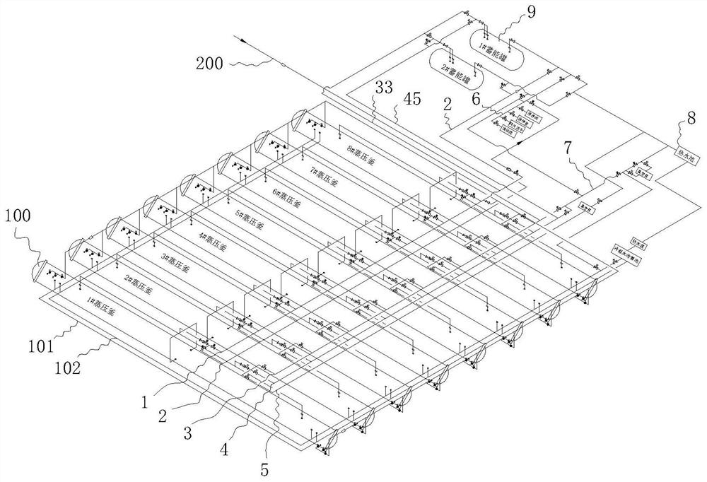
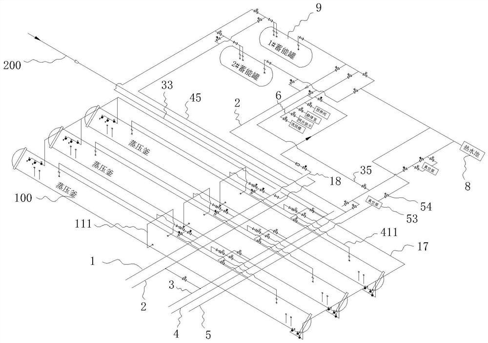
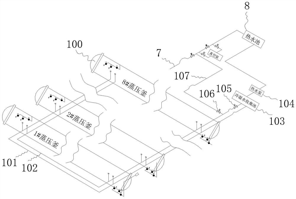
[0057] see Figure 1-11 , the present invention provides a technical solution: an automatic steam curing and gas distribution system for aerated concrete, comprising at least one autoclave 100, a main air pipe 1, an air intake pipe 2, an air discharge pipe 3, an exhaust pipe 4 and a vacuum pipe 5, The main gas pipe 1 communicates with the external pipeline 200 for transporting the steam of the power plant, and the main gas pipe 1 is connected with at least one...


PUM


Abstract

The invention discloses an aerated concrete automatic steam-curing gas distribution system. The system comprises at least one still kettle, a main gas pipe, a gas inlet pipe, a gas return pipe, a gas exhaust pipe, a vacuumizing pipe and at least one energy storage tank, wherein the main gas pipe communicates with an external pipeline used for conveying steam of a power plant, the main gas pipe is connected with at least one still kettle gas inlet pipe for supplying gas into the still kettle, a main gas electric stop valve, a gas inlet electric control valve and a gas inlet manual stop valve are sequentially mounted on the still kettle gas inlet pipe, the part, between the main gas electric stop valve and the air inlet electric regulating valve, of the still kettle air inlet pipe communicates with a first middle communicating pipe, and the first middle communicating pipe is provided with a first middle electric stop valve. According to the system, refined control of steam can be realized, good yield is ensured, steam can be utilized to the maximum extent, energy consumption is saved while the yield is increased, and the environmental protection requirement can be met.

Description

technical field [0001] The invention relates to the technical field of aerated concrete processing, in particular to an automatic steam curing and gas distribution system for aerated concrete. Background technique [0002] Air-entrained concrete is made of siliceous materials (sand, fly ash and silicon-containing tailings, etc.) , pre-curing, cutting, autoclaving, curing and other processes made of lightweight porous silicate products. Because it contains a large number of uniform and fine pores after being aerated, it is named aerated concrete. [0003] According to the application, aerated concrete can be divided into five types: non-load-bearing aerated concrete block, load-bearing aerated concrete block, aerated concrete insulation block, aerated concrete wall panel and aerated concrete roof panel. Due to the advantages of light bulk density, high thermal insulation performance, good sound-absorbing effect, certain strength and machinability, aerated concrete is one of...

Claims


Application Information

Patent Timeline
IPC IPC(8): B28B11/24B28B17/00F17D1/06F17D3/01
CPCB28B11/245B28B17/00B28B17/0063F17D1/06F17D3/01
Inventor 陈阿三王密文龚永林
Owner 苏州信义新型墙体材料有限公司
Why Eureka
Try Eureka