Gas separation device for geothermal energy recharge well

A gas separation and reinjection well technology, which is applied in degassed water/sewage treatment, water/sewage multi-stage treatment, mechanical oscillation water/sewage treatment, etc., can solve the waste of thermal energy area, blockage, and affect the recharge effect, etc. problems, to achieve the effects of reducing energy consumption, stabilizing the water outlet speed, and ensuring the utilization rate of heat

Active Publication Date: 2021-04-09
中石化新星双良地热能热电有限公司
View PDF3 Cites 2 Cited by
  • Summary
  • Abstract
  • Description
  • Claims
  • Application Information

AI Technical Summary

Problems solved by technology

[0003] Because the recharge water is in contact with the air, the air will dissolve in the recharge water; after the recharge water enters the recharge layer, the recharge water will be heated and the air in the recharge water will be separated, and the detached air will easily cause gas phase blockage to affect the recharge effect and cause heat District waste

Method used


Image

  • Gas separation device for geothermal energy recharge well
  • Gas separation device for geothermal energy recharge well
  • Gas separation device for geothermal energy recharge well

Examples


Embodiment 1

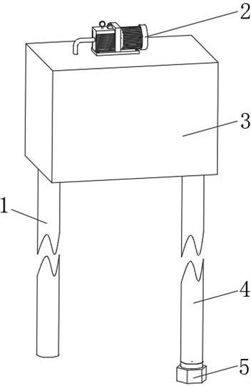
[0033] Example 1: Please refer to Figure 1-3 , this embodiment discloses a gas separation device for geothermal energy recharge wells, including a negative pressure pump 2 and a sealed housing 3, the sealed housing 3 is used to form a negative pressure environment, and the sealed housing 3 can withstand the difference in internal and external air pressure; The upper side of the casing 3 is provided with an exhaust hole communicating with the inside and outside thereof, and the exhaust hole communicates with the air inlet of the negative pressure pump 2 .

[0034] Specifically, such as figure 2 As shown, the lower side of the sealed housing 3 is provided with a water inlet hole 10 and a water outlet hole 12 that communicate with the inside and outside of the water inlet hole 10. connect.

[0035] Further, the height difference between the bottom end of the drain pipe 4 and the upper side of the inner cavity of the sealed housing 3 is greater than 10m.

[0036] The negative...

Embodiment 2

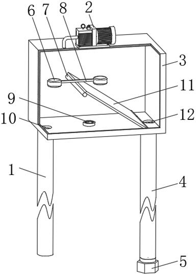
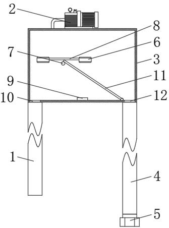
[0049] Embodiment two: if figure 2As shown, this embodiment discloses a gas separation device for geothermal energy reinjection wells. The bottom side of the inner cavity of the sealed housing 3 is connected to the rotating shaft or hinge at the lower end of the rotating plate 11. The rotating plate 11 is located between the water inlet hole 10 and the water outlet hole 12. A floating member is installed on the upper end of the rotating plate 11. The width of the rotating plate 11 is Both sides of the direction are slidingly connected with the inner wall of the sealed casing 3 , and the recharge water in the sealed casing 3 flows through the top of the rotating plate 11 .

[0050] When the sealing shell 3 is filled with refilling water, the refilling water will cause the floating part to float up, and the floating part will drive the upper end of the rotating plate 11 to move, and the distance between the bottom end of the rotating plate 11 and the liquid surface in the seali...

Embodiment 3

[0053] Embodiment three: as figure 2 and image 3 As shown, this embodiment discloses a gas separation device for geothermal energy recharge wells. On the basis of Embodiment 1 or Embodiment 2, an ultraviolet lamp 7 is installed in the sealed casing 3 of this embodiment; The cables pass through the sealed casing 3 and are electrically connected to the controller outside the sealed casing 3 .

[0054] The ultraviolet lamp 7 sterilizes the water flowing through the sealed casing 3 to prevent bacteria from corroding the pipeline or blocking the gaps in the heat storage area.

[0055] Iron bacteria: A group of bacteria that derive their energy from the oxidation of ferrous iron. The ferric hydroxide formed can be stored inside or outside the bacterial membrane sheath and can corrode pipes.

[0056] Saprophytic bacteria: They are "heterotrophic" bacteria. Under certain conditions, they obtain energy from organic matter, produce viscous substances, and accumulate and precipitate ...


PUM


Abstract

The invention discloses a gas separation device for a for geothermal energy recharge well, which comprises a negative pressure pump and a sealed shell, wherein an exhaust hole communicated with the inside and the outside of the sealed shell is formed in the upper side of the sealed shell, the exhaust hole is communicated with a gas inlet of the negative pressure pump, a water inlet hole and a water outlet hole communicated with the inside and the outside of the sealed shell are formed in the lower side of the sealed shell, the outer side of the water inlet hole is connected with the upper end of a water inlet pipe, the outer side of the water outlet hole is connected with the upper end of a drain pipe, and the height difference between the drain pipe and the sealed shell is greater than 10 m. The gas separation device for the geothermal energy recharge well is used for carrying out negative pressure gas separation treatment on the recharge water, the situation that the recharge effect is influenced due to gas phase blockage caused by air in the recharge water is avoided, and the heat utilization rate of a heat energy area is guaranteed.

Description

technical field [0001] The invention relates to the technical field of thermal energy equipment, in particular to a gas separation device for geothermal energy recharge wells. Background technique [0002] Geothermal energy is a natural resource with limited renewable capacity. In order to maintain the pressure of the thermal storage area, make full use of energy and reduce the environmental pollution caused by the direct discharge of geothermal fluid, the recharge water is often reinjected back into the thermal storage area through the recharge well. [0003] Because the recharge water is in contact with air, the air will dissolve in the recharge water; after the recharge water enters the recharge layer, the recharge water will be heated to make the air in the recharge water detach, and the detached air will easily cause gas phase blockage and affect the recharge effect, causing heat District waste. Contents of the invention [0004] The technical problem to be solved by...

Claims


Application Information

Patent Timeline
Patent Type & Authority Applications(China)
IPC IPC(8): C02F9/08
CPCC02F9/00C02F1/20C02F1/32C02F1/36Y02E10/10
Inventor 孙东斌孙文振姚金菊
Owner 中石化新星双良地热能热电有限公司
Why Eureka
Try Eureka