Rapid composite casting method for aerospace high-strength aluminum alloy

A composite casting and high-strength technology, applied in the field of aluminum alloy casting, can solve the problems of high-strength aluminum alloy castings that are prone to body cracks, and achieve the effects of meeting the requirements of rapid production, shortening the casting cycle, and high-quality preparation

Active Publication Date: 2021-04-16
BEIJING XINGHANG MECHANICAL ELECTRICAL EQUIP
View PDF6 Cites 0 Cited by
  • Summary
  • Abstract
  • Description
  • Claims
  • Application Information

AI Technical Summary

Problems solved by technology

[0005] In view of the above analysis, the present invention aims to provide a rapid composite casting method for aerospace high-strength aluminum alloys, which can solve the problem that high-strength aluminum alloy castings are prone to body cracks

Method used


Image

  • Rapid composite casting method for aerospace high-strength aluminum alloy
  • Rapid composite casting method for aerospace high-strength aluminum alloy
  • Rapid composite casting method for aerospace high-strength aluminum alloy

Examples


Embodiment 1

[0058] This embodiment provides a rapid composite casting method for aerospace high-strength aluminum alloys. The steps include:

[0059]Step 1: Use 3D printing technology to quickly prepare two sets of inner and outer sand molds according to the shape of the workpiece and the design of the casting process; Step 2: Select the appropriate material to prepare the transition layer; Step 3: Use automatic coating equipment to coat the 3D printed sand mold The transition layer; Step 4: Assemble the sand mold and pour high-strength aluminum alloy to complete the casting of high-strength aluminum alloy castings.

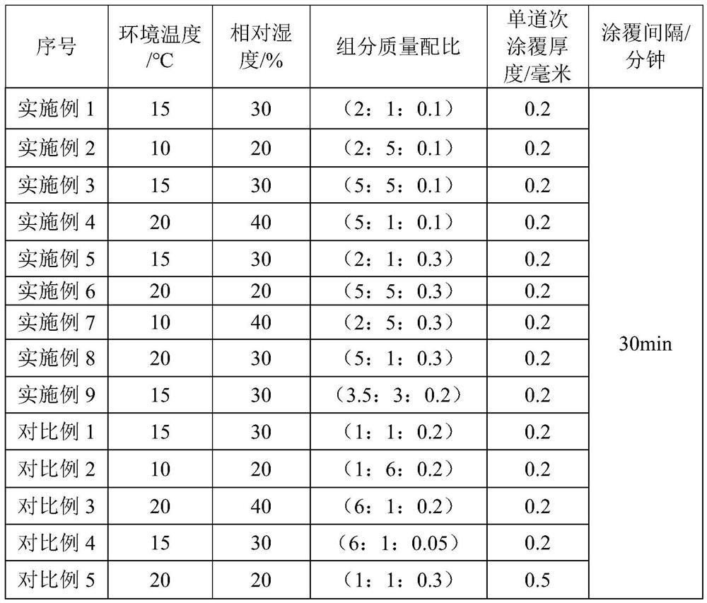
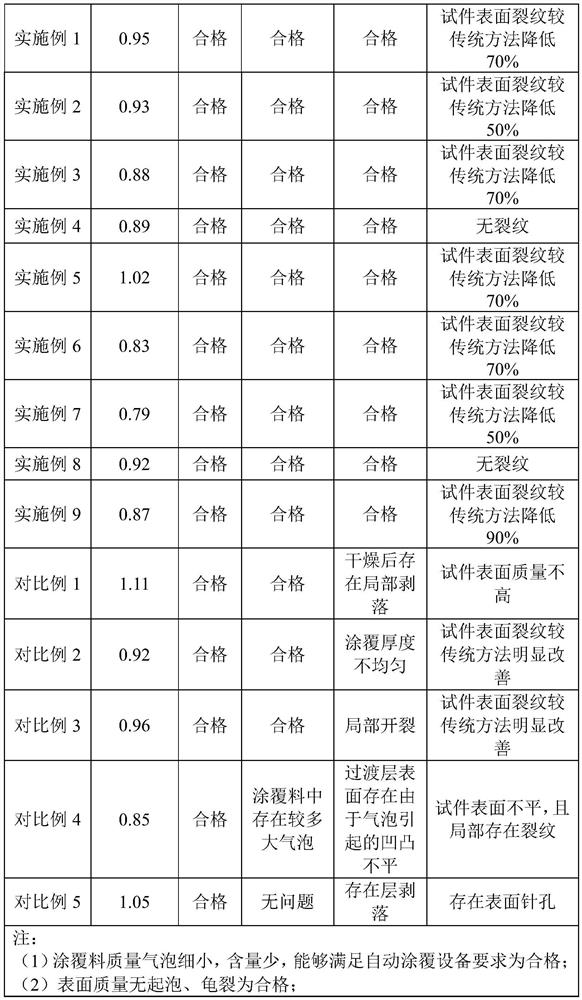
[0060] For the preparation of the transition layer in step 2, the transition layer includes refractory material A component, adhesive B component and defoamer C component, the refractory material is quartz sand, the bonding agent is silica sol, and the defoamer is n-octanol. Among them, the mass ratio of component A, component B and defoamer is 2:1:0.1.

[0061] The prepar...

Embodiment 2

[0068] This embodiment provides another rapid composite casting method for aerospace high-strength aluminum alloys. The other steps are the same as those in Embodiment 1 and will not be repeated here. The difference lies in the preparation of the transition layer in step 2. , The transition layer includes refractory material A component, adhesive B component and defoamer C component, the refractory material is quartz sand, the adhesive is silica sol, and the defoamer is n-octanol. Among them, the mass ratio of component A, component B and defoamer is 2:5:0.1.

[0069] In step 3, automatic coating equipment is used to coat the coating material on the surface of the test piece several times to obtain the required transition layer.

[0070] Step 301: Applying a transition layer coating material on the surface of the test piece by an automatic coating process to obtain a first coating; the ambient temperature during coating is 10° C., and the relative humidity is 20%.

[0071] In...


PUM

PropertyMeasurementUnit
thicknessaaaaaaaaaa
melting pointaaaaaaaaaa
strengthaaaaaaaaaa

Abstract

The invention discloses a rapid composite casting method for aerospace high-strength aluminum alloy, and belongs to the technical field of aluminum alloy casting. The rapid composite casting method solves the problem that a high-strength aluminum alloy casting in the existing casting molding technology easily generates body cracks. The rapid composite casting method comprises the following steps that 1, an inner sand mold and an outer sand mold are prepared by adopting a 3D printing technology; 2, a transition layer is prepared; 3, the sand mold is coated with the transition layer; and 4, the sand mold is assembled, high-strength aluminum alloy pouring is conducted, and casting of the high-strength aluminum alloy casting is completed. According to the rapid composite casting method for the aerospace high-strength aluminum alloy, by adding the transition layer on the sand mold, the cracking tendency of the high-strength aluminum alloy during casting is reduced, cracks on the surface of a test piece are reduced by 50%-90%, meanwhile, the sand mold is prepared through the 3D printing technology, the transition layer is coated through automatic coating equipment, and the casting period can be shortened by 10 days-15 days.

Description

technical field [0001] The invention belongs to the technical field of aluminum alloy casting, and in particular relates to a rapid compound casting method of aerospace high-strength aluminum alloy. Background technique [0002] Traditional aluminum alloy castings are generally produced by sand casting, especially resin sand casting, which can obtain products with better overall quality and performance, and has been widely used. [0003] As a new material, the high-strength aluminum alloy has a higher copper content than ordinary 1-series and 2-series aluminum alloys in order to achieve the goal of improving the alloy strength, resulting in a more serious overall crack tendency of the alloy than ordinary 1-series and 2-series cast aluminum alloys. If the traditional resin sand casting method is used for production, due to the high cooling rate of the sand mold, it is easy to crack during the solidification of the alloy liquid, resulting in unqualified internal quality of the...

Claims


Application Information

Patent Timeline
Patent Type & Authority Applications(China)
IPC IPC(8): B22C9/02B22C23/02B33Y10/00
Inventor 柳森
Owner BEIJING XINGHANG MECHANICAL ELECTRICAL EQUIP
Why Eureka
Try Eureka