Roll-to-roll surface rapid detection system for stainless steel substrate of CIGS battery piece
A detection system, stainless steel technology, applied in the direction of tension measurement, measuring device, optical test defect/defect, etc., can solve the problems of low work efficiency and high production cost, and achieve the effect of high detection efficiency
- Summary
- Abstract
- Description
- Claims
- Application Information
AI Technical Summary
Problems solved by technology
Method used
Image
Examples
Embodiment 1
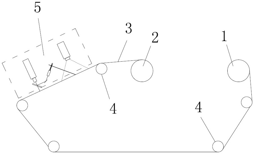
[0022] Example 1: A rapid detection system for the roll-to-roll surface of a CIGS cell stainless steel substrate, such as figure 1 shown. The device includes an unwinding shaft 1 and a winding shaft 2, and an ultra-thin stainless steel substrate coil 3 is retracted and transported between the unwinding shaft and the winding shaft. Between the unwinding shaft and the winding shaft, several conveying rollers 4 for conveying the base coil are arranged, and a surface detection system 5 is arranged between the two conveying rollers 4 closest to the winding shaft 2 . The base web 3 between the two conveying rollers 4 closest to the winding shaft 2 is arranged obliquely upward.
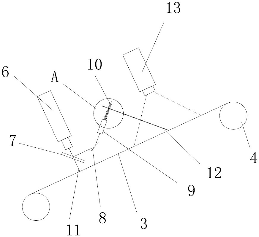
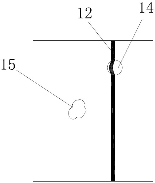
[0023] Such as figure 2 , 4 As shown, the surface detection system 5 includes a laser rangefinder 6, the laser rangefinder is perpendicular to the surface of the base coil 4, and a beam splitter 7 is arranged between the laser range finder 6 and the surface of the base coil 4, and the beam splitter The ...
Embodiment 2
[0026] Example 2, a roll-to-roll surface rapid detection system for CIGS cell stainless steel substrates, such as Image 6 shown. In the present embodiment, the laser range finder comprises a laser projection lens 18 and a laser retroreflection lens 19, a beam splitter 7 is arranged below the laser projection lens, a second mirror 20 is arranged below the laser retroreflection lens, and the second reflector is parallel to the beam splitter . The transmitted light beam of the laser rangefinder passing through the beam splitter is received after being reflected twice by the back of the beam splitter 7 and the second reflector 20 when returning, so as to ensure the intensity of the optical signal. The rest of the structure of this embodiment is the same as that of Embodiment 1.
PUM
| Property | Measurement | Unit |
|---|---|---|
| angle | aaaaa | aaaaa |
| angle | aaaaa | aaaaa |
Abstract
Description
Claims
Application Information
 - R&D
- Intellectual Property
- Life Sciences
- Materials
- Tech Scout
- Unparalleled Data Quality
- Higher Quality Content
- 60% Fewer Hallucinations
Browse by: Latest US Patents, China's latest patents, Technical Efficacy Thesaurus, Application Domain, Technology Topic, Popular Technical Reports.
© 2025 PatSnap. All rights reserved.Legal|Privacy policy|Modern Slavery Act Transparency Statement|Sitemap|About US| Contact US: help@patsnap.com


