
Unmanned aerial vehicle anti-collision device and airborne lens self-cleaning device and method

An anti-collision, unmanned aerial vehicle technology, applied in cleaning methods and utensils, cleaning methods using gas flow, chemical instruments and methods, etc., can solve problems such as reduced service life of wings, damaged wings, and inability to clean dust. Achieve the effect of improving buffering, maintaining cleanliness and reducing damage

Pending Publication Date: 2021-04-20
福建星图智控科技有限公司
View PDF0 Cites 0 Cited by
  • Summary
  • Abstract
  • Description
  • Claims
  • Application Information

AI Technical Summary

Problems solved by technology

[0004] The purpose of the present invention is to solve the existing problems in the prior art that most of the existing drones do not have a wing protection frame, so that the wings are easily damaged by the collision force, resulting in a reduction in the service life of the wings. The existing drones have a monitoring function. Most of the UAVs are not equipped with a dust cleaning device, which cannot clean the dust on the lens of the airborne optical equipment. The dust in the air will be adsorbed on the lens of the airborne optical equipment and affect the monitoring effect if the drone works a little longer. However, a kind of UAV anti-collision and airborne optical equipment lens self-cleaning device and its method are proposed

Method used


Image

  • Unmanned aerial vehicle anti-collision device and airborne lens self-cleaning device and method
  • Unmanned aerial vehicle anti-collision device and airborne lens self-cleaning device and method
  • Unmanned aerial vehicle anti-collision device and airborne lens self-cleaning device and method

Examples


Embodiment Construction

[0017] The following will clearly and completely describe the technical solutions in the embodiments of the present invention with reference to the accompanying drawings in the embodiments of the present invention. Obviously, the described embodiments are only some, not all, embodiments of the present invention.

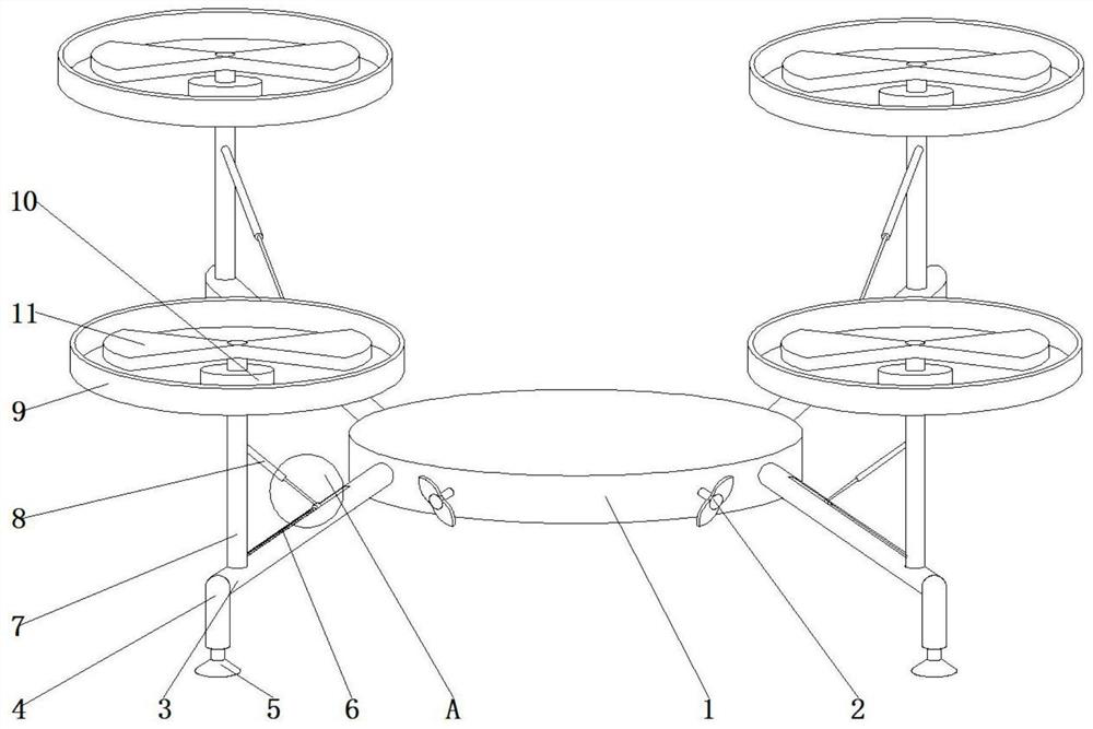
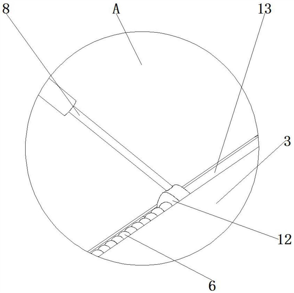
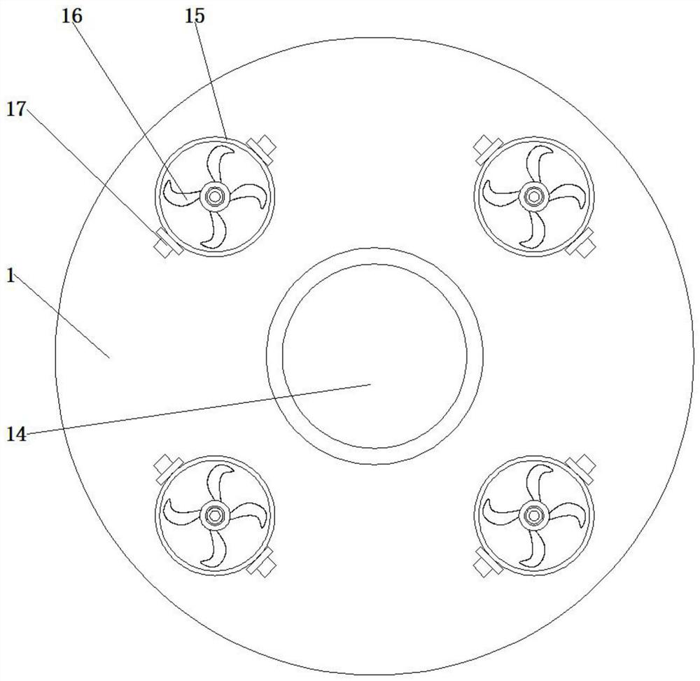
[0018] refer to Figure 1-3 , a UAV anti-collision device and airborne optical equipment lens self-cleaning device and method thereof, comprising a main body 1, one end on one side of the main body 1 is connected with a wind power fan 2, and a diagonal part on the outside of the main body 1 is fixedly connected with a connection Rod 3, the connecting rod 3 is located at one end of the wind power fan 2, one side of the connecting rod 3 is fixedly connected with the supporting leg 4, the bottom end of the supporting leg 4 is slidably connected with the suction cup 5, and the inner side of the connecting rod 3 is slidably connected with the buffer spring 6 One end of th...


PUM


Abstract

The invention relates to the field of safe flight of unmanned aerial vehicles, in particular to the field of unmanned aerial vehicle rotor wing anti-collision technology and unmanned aerial vehicle airborne optical equipment lens self-cleaning technology, which comprises a main body, a wind power generation fan is connected to one end of one side of the main body, and connecting rods are fixedly connected to opposite corners of the outer side of the main body; the connecting rod is located at one end of the wind power generation fan, one side of the connecting rod is fixedly connected with a supporting leg, the bottom end of the supporting leg is slidably connected with a suction cup, and the inner side of the connecting rod is slidably connected with a buffer spring. The device has the beneficial effect that the wings are protected. By arranging the wind power generation fan, the hollowed-out plate, the dust removal fan and the adjusting button, during use, the adjusting button is rotated to adjust the hollowed-out plate to an angle facing an airborne optical equipment lens, wind power drives the wind power generation fan to rotate to generate wind energy during takeoff, the wind energy is converted into electric energy, and dust on the lens is sucked away by suction force of the dust removal fan; and cleaning of the lens is facilitated to facilitate continuous work of equipment.

Description

technical field [0001] The invention relates to the technical field of drone safety, in particular to a drone anti-collision device, an airborne optical device lens self-cleaning device and a method thereof. Background technique [0002] With the development of society and economy, science and technology are constantly developing and innovating. UAV is one of the greatest inventions of people. UAV is a kind of unmanned vehicle controlled by radio remote control equipment and self-contained program control device. Airplanes, many places that are dangerous or inconvenient for people need to use drones to explore and perform other operations. The emergence of consumer-grade drones, especially industrial-application drones, has increased people's fun in life and expanded The public's vision also greatly reduces people's labor intensity and danger. [0003] Most of the existing UAVs do not have a wing protection frame, which makes the wings easily damaged by the collision force,...

Claims


Application Information

Patent Timeline
IPC IPC(8): B64C27/20B64D47/08F03D9/32F03D9/25B08B5/04
CPCY02E10/72Y02E10/728
Inventor 刘荣山
Owner 福建星图智控科技有限公司
Learn More