Preparation method of porous ceramic plate produced by utilizing nano ink-jet 3D printing technology

A porous ceramic plate, 3D printing technology, applied in ceramic products, applications, household appliances, etc., can solve problems such as sintering shrinkage deformation, pollution, and reduce product performance, achieve uniform sintering shrinkage, improve dimensional accuracy, and improve production efficiency. Effect

Inactive Publication Date: 2021-04-20
杭州普太科技有限公司
View PDF5 Cites 4 Cited by
  • Summary
  • Abstract
  • Description
  • Claims
  • Application Information

AI Technical Summary

Problems solved by technology

[0006] The present invention provides a method for preparing a porous ceramic plate produced by nano-inkjet 3D printing technology. However, it is difficult to make complex geometric shapes and assembly features in the X and Y axis directions; 3. Due to the characteristics of the mold design, the prior art ceramic porous plates need to be reinforced with rounded corners and large thickness on the outer edge of the plate Wall, to ensure that the geometric shape of the inner wall of the ceramic plate will not be damaged during demoulding; however, uneven wall thickness will cause sintering shrinkage and deformation, causing obvious gaps and boundaries when multiple ceramic plates are spliced, thereby reducing the performance of the spliced ​​product; For occasions that require large-scale application of porous ceramic plates, traditional ceramic plates cannot complete precise splicing applications; 4. When the mold is forming holes, factors such as mold and sintering shrinkage need to be considered, and the pores of actual products cannot achieve uniform pore diameters; 5. Now The mold and ceramic slurry in the existing technology cannot meet the needs of special occasions that require the same ceramic plate to have different wall thickness or lattice shape design; 6. The degreasing time of traditional ceramic slurry generally takes about 24 hours, and the efficiency is low; 7. . At present, most of the 3D printing technology needs manual removal of supports. For example, metal 3D printing needs to be removed by wire cutting, and plastic 3D printing basically requires manual cutting of supports; 7. There is still powder pollution in traditional ceramic slurry production , water pollution and air pollution

Method used


Image

  • Preparation method of porous ceramic plate produced by utilizing nano ink-jet 3D printing technology
  • Preparation method of porous ceramic plate produced by utilizing nano ink-jet 3D printing technology
  • Preparation method of porous ceramic plate produced by utilizing nano ink-jet 3D printing technology

Examples


Embodiment Construction

[0038] The technical solutions of the present invention will be further specifically described below through the embodiments and in conjunction with the accompanying drawings.

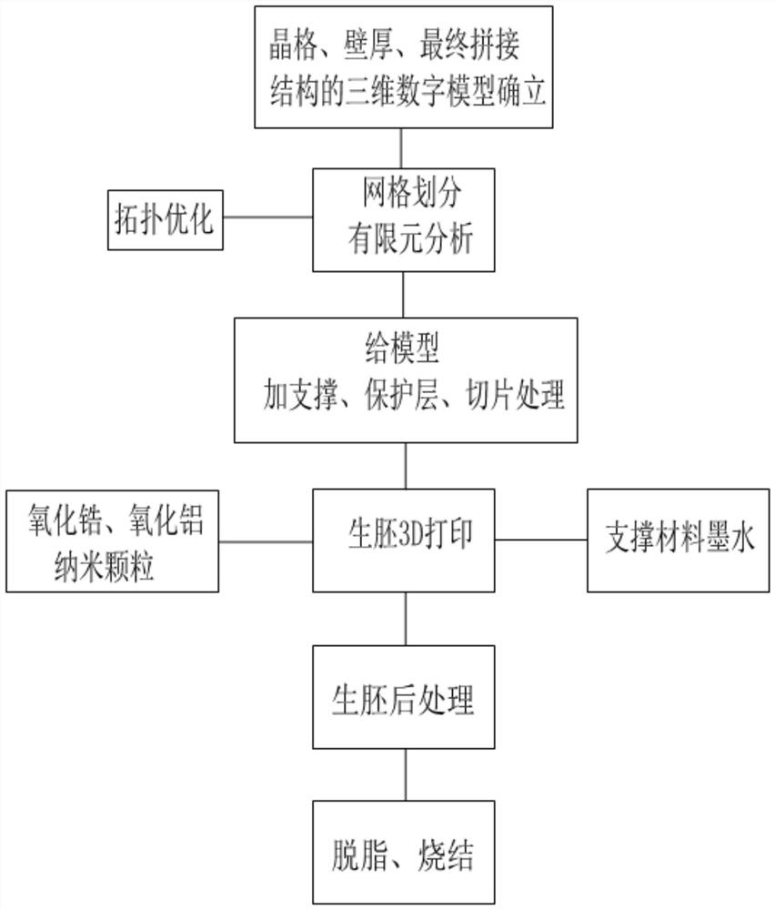
[0039] A method for preparing a porous ceramic plate produced by nano-inkjet 3D printing technology, such as figure 1 shown, including the following steps:

[0040] (1) Use 3D design software to establish a 3D digital model of the porous ceramic plate, including a 3D digital model of the lattice, wall thickness, and final spliced ​​structure of the porous ceramic plate. Combined with the actual specific application requirements, use UG, SolidWorks and other 3D design software to design the 3D digital model of the porous ceramic plate. In catalytic reaction applications, the specific surface area and pore size need to be adjusted according to the type of substance being catalyzed. If the catalyzed substance is a gas, generally speaking, the specific surface area as large as possible is required; if th...


PUM


Abstract

The invention discloses a preparation method of a porous ceramic plate produced by using a nano ink-jet 3D printing technology, and the method is characterized in that the method the following steps: establishing a three-dimensional digital model of the porous ceramic plate, meshing the three-dimensional digital model of the porous ceramic plate, topologically optimizing the three-dimensional digital model according to an analog result, and importing the model into a processing STL format 3d modeling editing repair tool to carry out support adding, protection layer adding, slicing processing, green body 3D printing, green body post-processing, degreasing and sintering on the model. According to the invention, splicing of a plurality of ceramic plates is realized, different wall thicknesses or different crystal lattice types exist on the same plate, the geometric structure shrinkage ratio is more controllable, degreasing and sintering of a formed green body are combined into one, the sintering efficiency is improved, large-batch post-treatment operation without intensive labor force is realized, and the production efficiency is improved.

Description

technical field [0001] The invention relates to a porous ceramic plate manufacturing technology, in particular to a method for preparing a porous ceramic plate produced by nano inkjet 3D printing technology. Background technique [0002] The porous ceramic plate is a plate product with a porous structure made of ceramic slurry after pressing or extruding and sintering. The types of holes on the market are mainly square holes and round holes in the Z direction (length, width, height). It is mostly used in chemical reaction, catalyst carrier, infrared radiation heating, combustion, lightweight plywood, heat insulation, high temperature and high pressure gas silencer, filtration, extrusion mold and acid and alkali resistance applications, etc. Among them, catalytic applications require as large a specific surface area as possible; lightweight applications require low relative density and high mechanical strength; applications such as heat insulation and noise reduction require...

Claims


Application Information

Patent Timeline
Patent Type & Authority Applications(China)
IPC IPC(8): C04B35/48C04B35/10C04B35/622B33Y70/10B33Y10/00B33Y50/02B33Y40/20C04B38/00
Inventor 陈铭洲周小坚
Owner 杭州普太科技有限公司
Why Eureka
Try Eureka