Low-water-gas-ratio CO conversion device and low-water-gas-ratio CO conversion method

A technology for conversion device and water-gas ratio, applied in the direction of climate sustainability, catalytic treatment of combustible gas, sustainable manufacturing/processing, etc., can solve the problems of affecting the service life of the catalyst, difficult to control the depth of the reaction, large steam consumption, etc. , to achieve the effect of reducing subsequent system equipment and pipeline loads, flexible and convenient air volume adjustment, and avoiding over-temperature phenomenon

Inactive Publication Date: 2021-04-27
SINOPEC NANJING ENG & CONSTR +1
View PDF7 Cites 4 Cited by
  • Summary
  • Abstract
  • Description
  • Claims
  • Application Information

AI Technical Summary

Problems solved by technology

Let part or all of the gas pass through the first reactor first, and add a large amount of steam at the mouth of the first reactor, usually making the water-gas ratio reach more than 1.4. The main problem of this technology: due to the high water-gas ratio and CO content , the driving force of the reaction is large, and the depth of the reaction is difficult to control
In actual operation, in the initial stage of catalyst use, sometimes it is necessary to use nitrogen dilution or increase the water-gas ratio or remove part of the catalyst to reduce the temperature, which affects the service life of the catalyst; at the same time, the steam consumption in the transformation section is large, and the heat recovery system of the transformation gas Finally, it is realized by setting up multiple heat exchangers, heating desalinated water and circulating water for cooling. The large amount of condensate in the transformed gas greatly increases the load and difficulty of downstream sewage treatment. The device consumes high energy and requires a large investment.

Method used


Image

  • Low-water-gas-ratio CO conversion device and low-water-gas-ratio CO conversion method

Examples


Embodiment 1

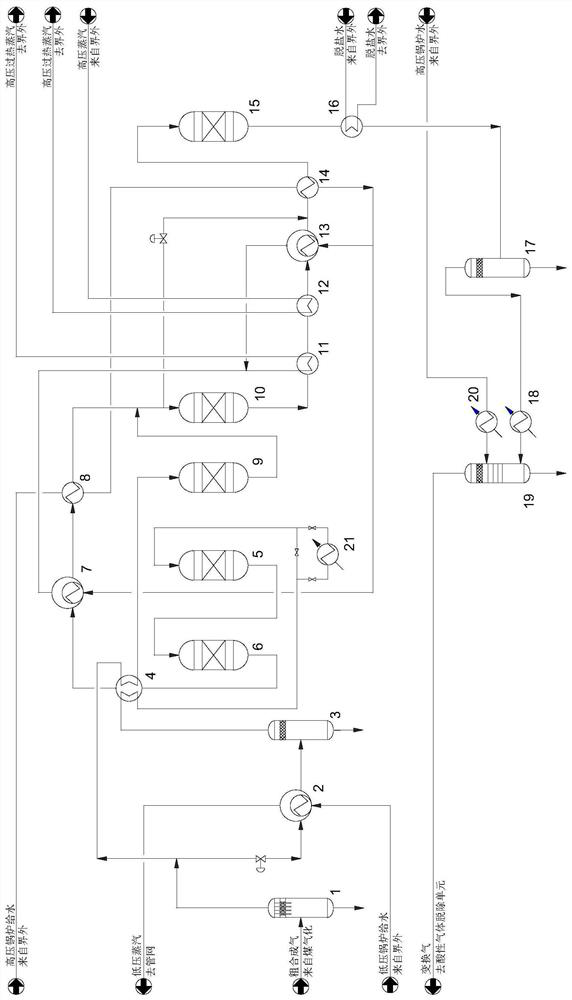
[0039] The 484880kg / h crude synthesis gas (206℃, 3.84MPa, water-gas ratio: 0.91) from the upstream coal gasification unit enters the 1# gas-liquid separator for gas-liquid separation, and is divided into two streams. The first stream is on the pipeline A flow regulating valve is set to control the flow distribution ratio of the first stream and the second stream to be 6:4. After the first stream (flow rate is 290928kg / h) passes through the steam generator, the by-product is 92503kg / h hLow-pressure saturated steam (165°C, 0.5MPa), after the water-gas ratio of the crude synthesis gas is reduced to 0.24, it enters the 2# gas-liquid separator for gas-liquid separation, and the top gas phase is heated to 200°C by the feed gas heater, After passing through the 1# detoxification tank, it enters the 1# shift furnace for carbon monoxide shift reaction. The inlet temperature of the 1# shift furnace is 200°C, and the outlet temperature of the shift gas at the outlet of the 1# shift furnac...

Embodiment 2

[0041] The 484880kg / h crude synthesis gas (206℃, 3.84MPa, water-gas ratio: 0.91) from the upstream coal gasification unit enters the 1# gas-liquid separator for gas-liquid separation, and is divided into two streams. The first stream is on the pipeline A flow regulating valve is provided to control the flow distribution ratio of the first stream and the second stream to be 5:5. After the first stream (flow rate is 242440kg / h) passes through the steam generator, the by-product is 82146kg / h hLow-pressure saturated steam (165°C, 0.5MPa), after the water-gas ratio of the crude synthesis gas is reduced to 0.2, it enters the 2# gas-liquid separator for gas-liquid separation, and the top gas phase is heated to 225°C by the feed gas heater, After passing through the 1# detoxification tank, it enters the 1# shift furnace for carbon monoxide shift reaction. The inlet temperature of the 1# shift furnace is 225°C, and the outlet temperature of the shift gas at the outlet of the 1# shift fu...

Embodiment 3

[0043] The 484880kg / h crude synthesis gas (206℃, 3.84MPa, water-gas ratio: 0.91) from the upstream coal gasification unit enters the 1# gas-liquid separator for gas-liquid separation, and is divided into two streams. The first stream is on the pipeline A flow regulating valve is provided to control the flow distribution ratio of the first stream and the second stream to be 4:6. After the first stream (flow rate is 193952kg / h) passes through the steam generator, the by-product is 55218kg / h hLow-pressure saturated steam (165°C, 0.5MPa), after the water-gas ratio of the crude synthesis gas is reduced to 0.3, it enters the 2# gas-liquid separator for gas-liquid separation, and the top gas phase is heated to 260°C by the feed gas heater, After passing through the 1# detoxification tank, it enters the 1# shift furnace for carbon monoxide shift reaction. The inlet temperature of the 1# shift furnace is 260°C, and the outlet temperature of the shift gas at the outlet of the 1# shift fu...


PUM


Abstract

The invention belongs to the technical field of CO conversion processes of coal chemical industry devices, and relates to a low-water-gas-ratio CO conversion device and a low-water-gas-ratio CO conversion method. Aiming at high-CO crude synthesis gas from a coal gasification device, crude gas is reasonably divided into two streams by adopting a flow splitting mode, and the water-gas ratio of one stream is reduced, so that the reaction depth of a 1# shift converter and the hot spot temperature of a bed layer are controlled, and the overtemperature phenomenon of a reactor is avoided. After the other stream is mixed with the gas from the 1# shift converter, the CO concentration is greatly reduced, and the possibility of methanation reaction of a 2# shift converter is greatly reduced. The technological process has the advantages of being high in upstream device operation fluctuation resistance, good in system energy integration effect, remarkable in energy conservation and consumption reduction and the like.

Description

technical field [0001] The invention belongs to the technical field of CO conversion technology for coal chemical plants, and relates to a low water-gas ratio CO conversion device and method. Background technique [0002] In the coal gasification supporting equipment, the carbon monoxide conversion device adjusts the hydrogen-carbon ratio of the crude gas produced by the gasification device through the conversion reaction to meet the needs of downstream products. The selection of its process technology should combine the crude gas produced by different gasification processes The characteristics of the equipment should also take into account the requirements of subsequent devices and downstream products. The composition of crude gas produced by various gasification processes is quite different. Even for the same downstream product, the conversion process technologies matched with different gasification processes are also different. The selection of CO conversion process shou...

Claims


Application Information

Patent Timeline
Patent Type & Authority Applications(China)
IPC IPC(8): C10K3/04
CPCC10K3/04Y02P20/10
Inventor 兰荣亮汪根宝马炯谢东升王靓薛白
Owner SINOPEC NANJING ENG & CONSTR
Why Eureka
Try Eureka