Method for deeply removing arsenic in waste SCR catalyst acid system

A technology of SCR catalyst and acidic system, applied in chemical instruments and methods, separation methods, solid waste removal, etc., can solve the problems of reducing investment and operating costs, low arsenic removal efficiency, etc., achieve simple process flow, avoid waste brine , easy-to-operate effect

Active Publication Date: 2021-04-30
INST OF PROCESS ENG CHINESE ACAD OF SCI
View PDF9 Cites 5 Cited by
  • Summary
  • Abstract
  • Description
  • Claims
  • Application Information

AI Technical Summary

Problems solved by technology

[0007] In view of the problems existing in the prior art, the present invention provides a method for deep arsenic removal in the acidic system of the spent SCR catalyst. The present invention reacts the spent SCR catalyst powder with a cleaning solution containing acidic substances and additives to solve the problem of It solves the problem of low arsenic removal efficiency in the acidic system of spent SCR catalysts, realizes the simultaneous removal of toxic components of arsenic, potassium, sodium and iron, and has a short process flow and almost no waste brine, which effectively reduces investment and operation costs and meets the requirements of The development trend of green and environmental protection

Method used


Image

  • Method for deeply removing arsenic in waste SCR catalyst acid system
  • Method for deeply removing arsenic in waste SCR catalyst acid system
  • Method for deeply removing arsenic in waste SCR catalyst acid system

Examples


Embodiment 1

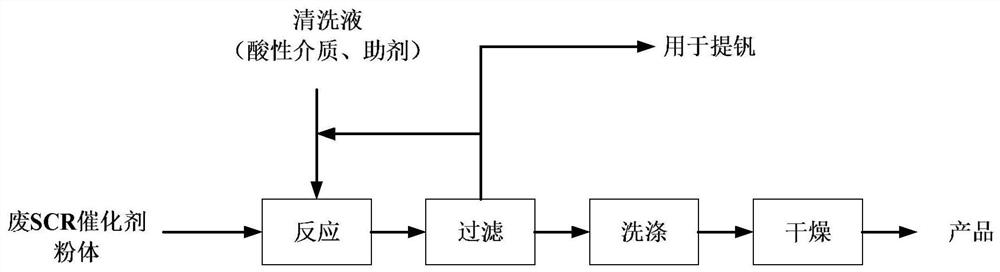
[0035] This embodiment provides a method for deep arsenic removal in an acidic system of a spent SCR catalyst, the method comprising the following steps:

[0036] (1) Grinding the waste SCR catalyst after deashing, then adding the waste SCR catalyst powder into the cleaning liquid containing 10% sulfuric acid and 1% sodium sulfide, the mass ratio of the cleaning liquid to the waste SCR catalyst powder 2:1, after reacting at 30°C for 3h, filter;

[0037] (2) washing and drying the solid phase obtained by filtration to obtain the product.

Embodiment 2

[0039] This embodiment provides a method for deep arsenic removal in an acidic system of a spent SCR catalyst, the method comprising the following steps:

[0040] (1) Grinding the waste SCR catalyst after deashing, then adding the waste SCR catalyst powder into the cleaning solution containing 15% hydrochloric acid and 0.5% potassium thiosulfate, the difference between the cleaning solution and the waste SCR catalyst powder The mass ratio is 10:1, after reacting at 60°C for 6 hours, filter;

[0041] (2) washing and drying the solid phase obtained by filtration to obtain the product.

Embodiment 3

[0043] This embodiment provides a method for deep arsenic removal in an acidic system of a spent SCR catalyst, the method comprising the following steps:

[0044] (1) Grinding the waste SCR catalyst after deashing, then adding the waste SCR catalyst powder into the cleaning liquid containing 11% oxalic acid and 2% sodium sulfite, the mass ratio of the cleaning liquid and the waste SCR catalyst powder is 8:1, after reacting at 100°C for 8 hours, filter;

[0045] (2) washing and drying the solid phase obtained by filtration to obtain the product.


PUM


Abstract

The invention relates to a method for deeply removing arsenic in a waste SCR (Selective Catalytic Reduction) catalyst acid system. The method comprises the following steps: (1) grinding a waste SCR catalyst subjected to ash removal, adding waste SCR catalyst powder into a cleaning solution containing an acid substance and an assistant, reacting, and filtering; and (2) washing and drying a filtered solid phase to obtain the product. According to the method provided by the invention, synchronous removal of toxic components such as arsenic, potassium, sodium and iron is realized by adopting the cleaning solution containing the acid substance and the assistant, the removal rate can reach 95% or above, and the content of the toxic components in the product is less than 200ppm; and the method is simple in technological process and easy to operate, avoids alternate use of acid and alkali and generation of waste brine, reduces the production cost and the environmental protection pressure, and conforms to the development trend of environmental protection.

Description

technical field [0001] The invention relates to the field of resource utilization of solid waste, in particular to a method for deep arsenic removal in an acidic system of a spent SCR catalyst. Background technique [0002] Selective Catalytic Reduction (SCR) is the most important method for controlling the emission of nitrogen oxides in coal-fired power plants in my country, and the catalyst is the key to the SCR method. At present, the waste SCR denitrification catalyst is produced in a huge amount, which is included in the management of hazardous waste. It needs to be recycled and reused to turn waste into treasure and save resources. There are currently two main routes for resource recovery and utilization of spent SCR catalysts. One is to separate and recover titanium, tungsten and vanadium to prepare corresponding metal oxides, and the other is to recycle them in the form of titanium and tungsten powder for new SCR after purification. Catalyst production. Among them,...

Claims


Application Information

Patent Timeline
Patent Type & Authority Applications(China)
IPC IPC(8): B09B3/00B09B5/00B01D53/86B01D53/56
CPCB09B3/00B09B5/00B01D53/8628Y02P20/584
Inventor 李会泉王兴瑞赵晨武文粉
Owner INST OF PROCESS ENG CHINESE ACAD OF SCI
Why Eureka
Try Eureka