Flame stabilizer, radial flame stabilizer and combustion chamber

A flame stabilizer and stabilizer technology, applied in the field of turbo/ramjet combined engine and turbofan engine afterburner/ramjet combustor, which can solve the problem of increasing the thermal burden of fuel nozzles and flame stabilizers, increasing resistance loss, and preventing fuel from evaporating and igniting To achieve the effect of improving the atomization and evaporation performance, improving the ability of circumferential diffusion, and expanding the stable working range

Active Publication Date: 2021-04-30
NANJING UNIV OF AERONAUTICS & ASTRONAUTICS
View PDF11 Cites 11 Cited by
  • Summary
  • Abstract
  • Description
  • Claims
  • Application Information

AI Technical Summary

Problems solved by technology

Therefore, it is difficult for the flame behind the radial stabilizer to expand in the circumferential direction, resulting in difficulty in the circumferential cross-flame between adjacent stabilizers; (2) under high temperature flow, the fuel is easily evaporated after being sprayed from the nozzle hole, and on the one hand, it is prone to thermal spontaneous combustion; On the other hand, small oil droplets and gas-phase fuel follow well with the airflow, and their circumferential penetration is weak, so the fuel is mainly concentrated near the downstream of the nozzle position; while under high-speed flow, the penetration depth of fuel is small, and the oil mist is also unable to Diffusion along the circumferential direction is not conducive to the uniform and reasonable distribution of fuel oil on the entire flow section, which reduces the combustion efficiency; (3) When using conventional radial flame stabilizers, in order to improve the ability of circumferential flame joints, the distance between the stabilizers must be shortened
On the premise of not changing the slot width of the stabilizer, it is necessary to increase the number of stabilizers, increase the blockage ratio, and increase the resistance loss; while keeping the blockage ratio unchanged, the slot width of the stabilizer must be reduced, which reduces the stability The flame stability performance of the device
[0006] The conventional design method of oil supply, blending and stabilization in space segmented to perform their respective duties is prone to thermal spontaneous combustion and ablation of the stabilizer in the high-temperature airflow of the advanced afterburner; while in the low-temperature high-speed airflow of the ram combustor Medium, the fuel is not easy to evaporate and ignite, and it is difficult to burn stably
Most modern afterburners and ramcombustors use stabilizers with an integrat

Method used


Image

  • Flame stabilizer, radial flame stabilizer and combustion chamber
  • Flame stabilizer, radial flame stabilizer and combustion chamber
  • Flame stabilizer, radial flame stabilizer and combustion chamber

Examples


Embodiment 1

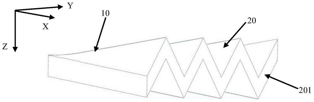
[0028] Embodiment 1: as figure 1 As shown, a flame stabilizer according to the present invention includes a stabilizer main body 10, and the stabilizer main body 10 has a periodic undulating surface 20, and the periodic undulating surface 20 includes several undulating units 201, and several undulating units 201 Arranged radially along the stabilizer main body 10 (the radial direction of the stabilizer main body 10 described in the present invention is figure 1 X-axis extension direction), each undulation unit 201 fluctuates toward the direction away from the stabilizer main body 10, and the far away from the stabilizer main body 10 described here is away from the plane direction where the stabilizer main body 10 is located, (stabilizer main body 10 on the plane with figure 1 The planes formed by the middle X axis-Y axis are parallel), and the wave directions of adjacent wave units 201 are opposite, and each wave unit 201 is from the front end to the rear end direction (the X...

Embodiment 2

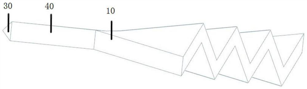
[0031] Embodiment 2: as Figure 3-5 As shown, utilizing the stabilizer main body 10 of embodiment 1, the present invention provides a radial flame stabilizer 1, comprising a leading edge section 30, a long straight section 40 arranged at the rear end of the leading edge section 30 and a long straight section arranged at the long straight section 40 rear end of the stabilizer main body 10 as described in Embodiment 1.

[0032] The leading edge section 30 in this embodiment is a V-shaped structure, along the direction from front to back, the distance between the two sides of the V-shaped structure gradually increases, and a hollow long straight section is provided at the tail end of the leading edge section 30 40. The long straight section 40 is roughly a hollow long cylinder, and the two sides of the long straight section 40 are provided with several oil injection holes 401. In an optional embodiment, the oil injection holes 401 are arranged along the radial direction on the side...


PUM


Abstract

The invention discloses a flame stabilizer, a radial flame stabilizer and a combustion chamber. According to the flame stablizer, a stabilizer body comprises a periodic fluctuation profile, wherein the periodic fluctuation profile comprises a plurality of fluctuation units distributed in the radial direction; each fluctuation unit fluctuates in the direction away from the stabilizer body; the fluctuation directions of the adjacent fluctuation units are opposite; and the fluctuation height of each fluctuation unit is gradually increased in the direction from the front end to the rear end. The flame stablizer integrates the functions of mixing, oil supply and flame stabilization; the fuel oil retention time can be prolonged; the fuel oil atomization and evaporation properties can be improved; the mixing of fuel oil and air can be enhanced; the circumferential cross-flame capacity can be improved; the more sufficient combustion in the combustion chamber can be achieved; the working efficiency of the combustion chamber can be improved; the outlet temperature can be more uniform; and the stable working range of an afterburner can be expanded.

Description

technical field [0001] The invention belongs to the technical field of turbo / ramjet combined engine and turbofan engine afterburner / ramjet combustion chamber, and in particular relates to a flame stabilizer, a radial flame stabilizer and a combustion chamber. Background technique [0002] Turbine-based combined cycle (TBCC) as an air-breathing engine has the advantages of wide flight range, conventional take-off and landing, and reusability, and is considered to be the most promising hypersonic vehicle at this stage. powerplant. Due to the large variation of the bypass ratio in the whole working range, the temperature of the incoming flow inside the multi-mode combustion chamber of the TBCC engine is low and the local flow velocity is too high. Under such flow conditions, how to achieve stable ignition and cross-flame, and reduce the flow resistance loss in the non-afterburner state is the goal of the afterburner development at present and in the future. [0003] The flame...

Claims


Application Information

Patent Timeline
IPC IPC(8): F23R3/20F23R3/42
CPCF23R3/20F23R3/42
Inventor 范育新刘琛
Owner NANJING UNIV OF AERONAUTICS & ASTRONAUTICS
Why Eureka
Try Eureka