Air source heat pump unit

An air source heat pump and unit technology, applied in the field of heat pumps, can solve problems such as underutilization of low-grade waste heat of flue gas, complex pipelines of the system, etc., and achieve the effect of avoiding unstable or incapable heating and ensuring stability

Active Publication Date: 2021-04-30
SHANGHAI AIRUTE AIR CONDITIONING SYST
View PDF8 Cites 8 Cited by
  • Summary
  • Abstract
  • Description
  • Claims
  • Application Information

AI Technical Summary

Problems solved by technology

When defrosting in winter, multiple valves are required to switch, the system piping is complicated, and the low-grade waste heat of flue gas is not fully utilized

Method used


Image

  • Air source heat pump unit
  • Air source heat pump unit
  • Air source heat pump unit

Examples


Embodiment 1

[0030] This embodiment provides an air source heat pump unit.

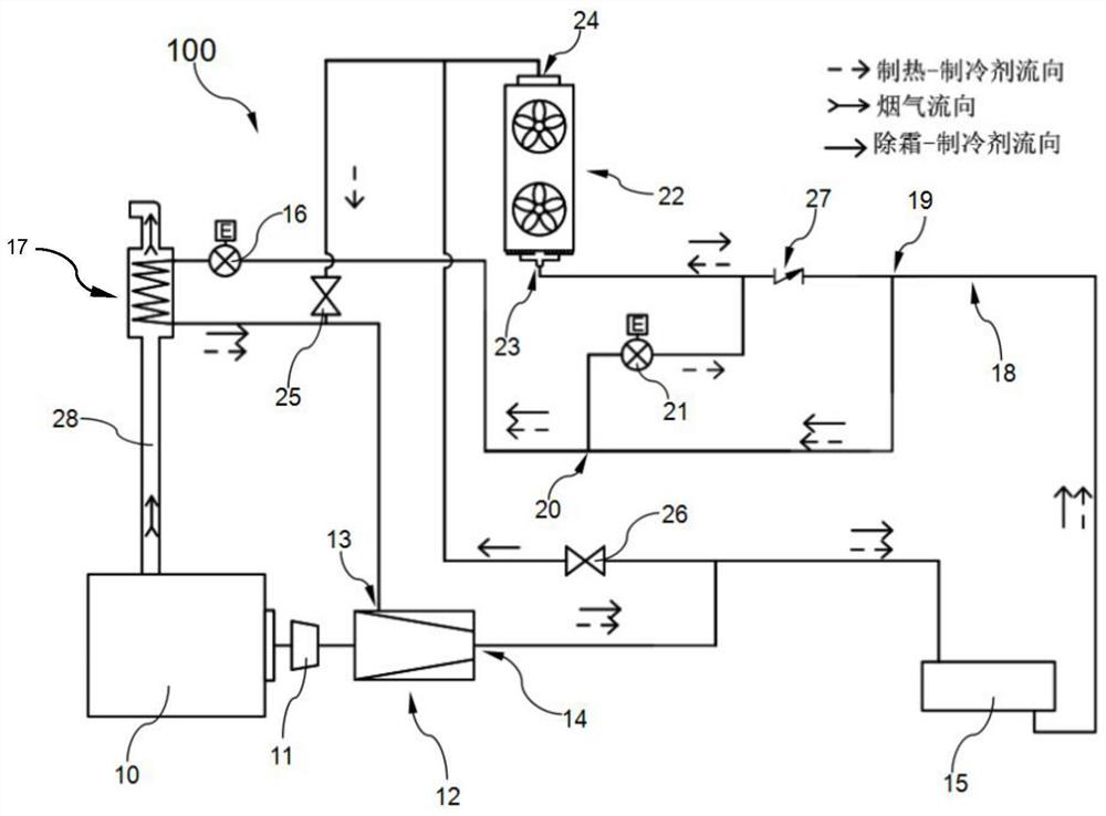
[0031] figure 1 It is a schematic diagram of the connection and flow of the air source heat pump unit in this embodiment.

[0032] Such as figure 1 As shown, the air source heat pump unit 100 includes a gas engine 10, a transmission device 11, a compressor 12, a first heat exchanger 15, a first throttle valve 16, a flue gas heat exchanger 17, a first pipeline 18, a second Throttle valve 21 , second heat exchanger 22 , first switching valve 25 , second switching valve 26 , and third switching valve 27 .

[0033] The output end of the gas engine 10 is connected together with the compressor 12 through the transmission device 11, and the compressor 12 is driven to compress the refrigerant gas inside it. The speed of the gas engine 10 is continuously adjustable, and the speed of the compressor 12 can be adjusted according to the needs of different operating conditions by adjusting the speed of the gas engine 10. Th...

Embodiment 2

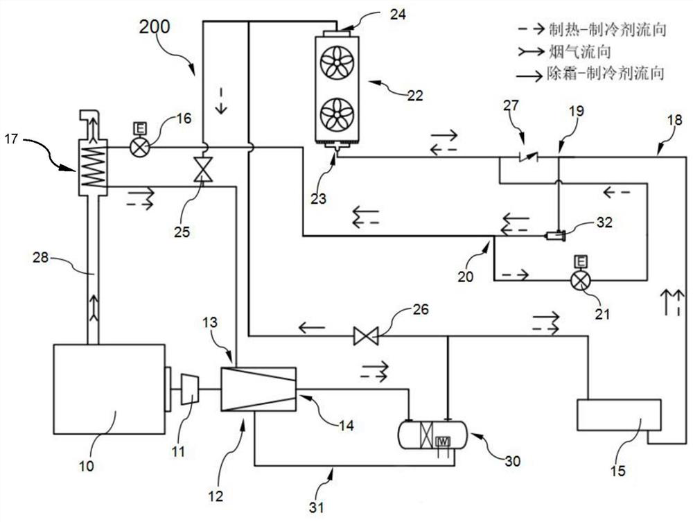
[0050] This embodiment provides an air source heat pump unit. The difference between the air source heat pump unit and the air source heat pump unit 100 in Embodiment 1 is that the air source heat pump unit 200 in this embodiment (see figure 2 ) also includes an oil separator 30, a lubricating oil circuit 31 and a filter drier 32. The first heat exchanger 15 of this embodiment does not include the oil separator 30 .

[0051] Other structures in this embodiment are the same as in Embodiment 1, and the same numbers are assigned to the same structures.

[0052] figure 2 It is a schematic diagram of the connection and flow of the air source heat pump unit 200 in this embodiment.

[0053] Such as figure 2 As shown, the oil separator 30 has an oil refrigerant inlet, an oil refrigerant outlet and a lubricating oil outlet, the oil refrigerant inlet is connected to the exhaust port 14, the oil refrigerant outlet is connected to the first refrigerant inlet, and the lubricating oil...

Embodiment 3

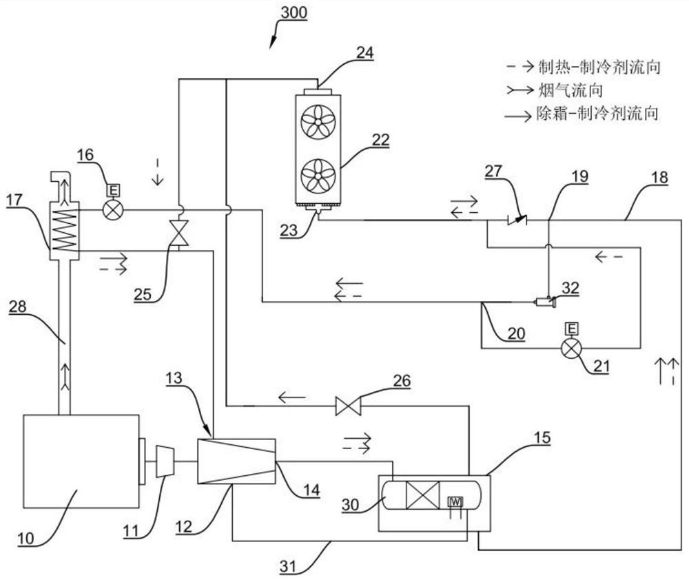
[0063] This embodiment provides an air source heat pump unit. The difference between the air source heat pump unit and the air source heat pump unit 200 in Embodiment 2 is that the first heat exchanger 15 of the air source heat pump unit 300 in this embodiment includes Oil separator 30. Other structures in this embodiment are the same as in Embodiment 1, and the same numbers are given to the same structures.

[0064] image 3 It is a schematic diagram of the connection and flow of the air source heat pump unit in the third embodiment.

[0065] Such as image 3 As shown, the oil separator 30 is arranged in the first heat exchanger 15, and has an oil component refrigerant inlet, an oil component refrigerant outlet and a lubricating oil discharge port. The refrigerant gas containing lubricating oil is discharged from the exhaust port 14 of the compressor 12, enters the first refrigerant inlet, and then enters the oil separator 30 through the oil-separated refrigerant inlet, an...


PUM


Abstract

The invention belongs to the technical field of heat pumps, and provides an air source heat pump unit. The air source heat pump unit is provided with a gas engine, a transmission device, a compressor, a first throttling valve, a second throttling valve, a first heat exchanger, a second heat exchanger and a smoke heat exchanger, wherein a first switching valve is arranged between the second heat exchanger and an air suction port; a second switching valve is arranged between the second heat exchanger and an exhaust port; a third switching valve is arranged between the second heat exchanger and the smoke heat exchanger; when the first switching valve is opened, the second switching valve and the third switching valve are closed, and the unit is in a heating mode; when the first switching valve is closed, the second switching valve and the third switching valve are opened, and the unit is in a defrosting mode; and the modes are controlled to be switched through the first switching valve and the second switching valve, internal leakage of refrigerants is avoided, equipment pipelines are simpler, the gas resistance of the refrigerants is reduced, and the work efficiency of the unit is improved. The air source heat pump unit is simple in equipment pipeline and stable in heat supply, defrosting can be conducted while heat supply is conducted, energy consumption is reduced, and the service life of equipment is prolonged.

Description

technical field [0001] The invention belongs to the technical field of heat pumps, and in particular relates to an air source heat pump unit. Background technique [0002] Currently widely used hot water boilers consume a lot of primary energy, have high operating costs, and generate a large amount of carbon emissions. Air source heat pumps driven by gas engines have the characteristics of high efficiency, low operating costs, and low carbon emissions. Therefore, it is an inevitable choice to replace gas-fired hot water boilers with high-efficiency gas engine-driven air source heat pumps. Engine-driven air source heat pumps have significant economic and environmental benefits. However, the air source heat pump also has some shortcomings. When the air source heat pump is operated in the outdoor low temperature and high humidity area, the moisture in the air below the dew point temperature will condense on the outer surface of the evaporator. If the temperature of the evapora...

Claims


Application Information

Patent Timeline
Patent Type & Authority Applications(China)
IPC IPC(8): F25B30/06F25B41/20F25B41/42F25B47/02
CPCF25B30/06F25B47/02F25B2600/25
Inventor 张小力
Owner SHANGHAI AIRUTE AIR CONDITIONING SYST
Why Eureka
Try Eureka