Ammonia spraying static mixer and dust removal method
A static mixer and static mixing technology, applied in the direction of fluid mixers, chemical instruments and methods, mixers, etc., can solve the problems of back-end equipment blockage, inability to effectively remove dust, etc., reduce production and installation costs, and realize modularization The effect of mass production, reducing the deviation of gas velocity distribution and ammonia concentration distribution
- Summary
- Abstract
- Description
- Claims
- Application Information
AI Technical Summary
Problems solved by technology
Method used
Image
Examples
Embodiment 1
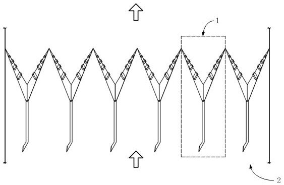
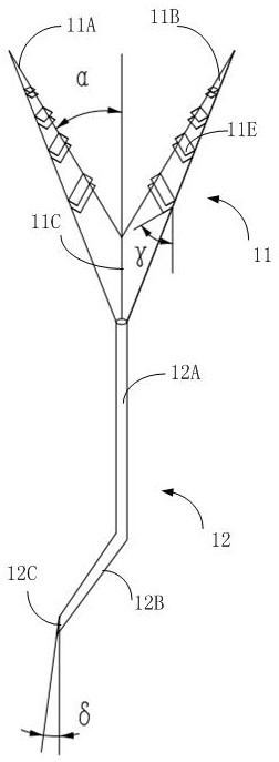
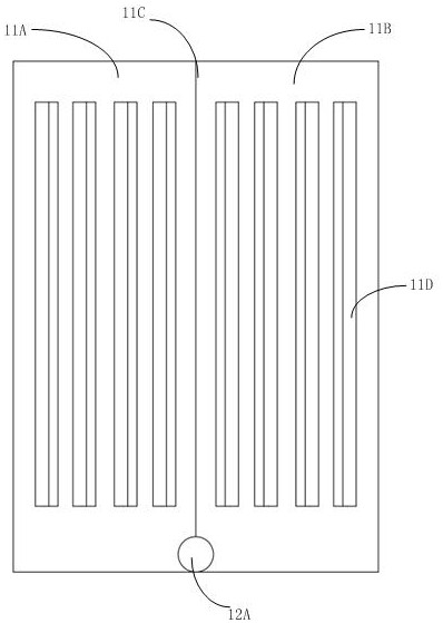
[0048] Such as Figure 1~5 In the device embodiment shown, the ammonia injection static mixer of the present invention is composed of a layer of ammonia injection static mixer, and the angle between the right-angled trapezoidal wing plates (that is, the first wing plate 11A and the second wing plate 11B) and the vertical direction is α is 30°, the included angle β between the right-angled trapezoidal hypotenuse of the first wing plate 11A and the second wing plate 11B and the horizontal direction is 15°, and the top of the first wing plate 11A and the second wing plate 11B are provided with four The opening 11D, the shape of the opening 11D is a rectangle, the opening faces the side of the opposite wing plate and is provided with a deflector 11E, the angle γ between the deflector 11E and the vertical direction is 75°, the wedge-shaped surface at the lower end of the inclined pipe section 12B is in line with the vertical The angle δ between the directions is 15°.
[0049] A ce...
Embodiment 2
[0051] Such as Figure 6 In the device embodiment shown, the ammonia injection static mixer of the present invention is made up of two layers of ammonia injection static mixers, i.e. the first layer of ammonia injection static mixer F1 and the second layer of ammonia injection static mixer F2, the two layers of ammonia injection static mixer The static mixers share the same hollow pipe 12, including a vertical pipe section 12A, an inclined pipe section 12B and a baffle 12C. The ratio of the cross-sectional area of the upper surface of the V-shaped plate 11 of the second layer of ammonia-injected static dust removal mixer to the upper surface cross-sectional area of the V-shaped plate of the first layer of ammonia-injected static dust removal mixer is 1.5:1.
[0052] further as Figure 2-5 As shown, the angle α between the right-angled trapezoidal wing plates (that is, the first wing plate 11A and the second wing plate 11B) and the vertical direction is 45°, and the right-...
Embodiment 3
[0055] Such as Figure 7 In the device embodiment shown, the ammonia injection static mixer of the present invention is made up of three layers of ammonia injection static mixers, namely the first layer of ammonia injection static mixer F1, the second layer of ammonia injection static mixer F2 and the third layer of ammonia injection static mixer. The ammonia static mixer F3 shares the same hollow tube 12 among the three layers of ammonia injection static mixers, including a vertical tube section 12A, an inclined tube section 12B and a baffle 12C. The cross-sectional area ratio of the V-shaped plate 11 upper surface of the second layer of ammonia-sprayed static dedusting mixer to the V-shaped plate of the first-layer ammonia-sprayed static dedusting mixer is 2:1, and the third layer of ammonia-sprayed static dedusting mixer is 2:1. The ratio of the cross-sectional area of the upper surface of the V-shaped plate 11 of the dust removal mixer to the cross-sectional area of th...
PUM
 Abstract
Description
Claims
Application Information
 - R&D
- Intellectual Property
- Life Sciences
- Materials
- Tech Scout
- Unparalleled Data Quality
- Higher Quality Content
- 60% Fewer Hallucinations
Browse by: Latest US Patents, China's latest patents, Technical Efficacy Thesaurus, Application Domain, Technology Topic, Popular Technical Reports.
© 2025 PatSnap. All rights reserved.Legal|Privacy policy|Modern Slavery Act Transparency Statement|Sitemap|About US| Contact US: help@patsnap.com


