Resonant cavity type optical fiber gas sensor
A gas sensor, resonant cavity technology, applied in the direction of color/spectral characteristic measurement, etc., can solve the problem of low detection sensitivity
- Summary
- Abstract
- Description
- Claims
- Application Information
AI Technical Summary
Problems solved by technology
Method used
Image
Examples
Embodiment 1
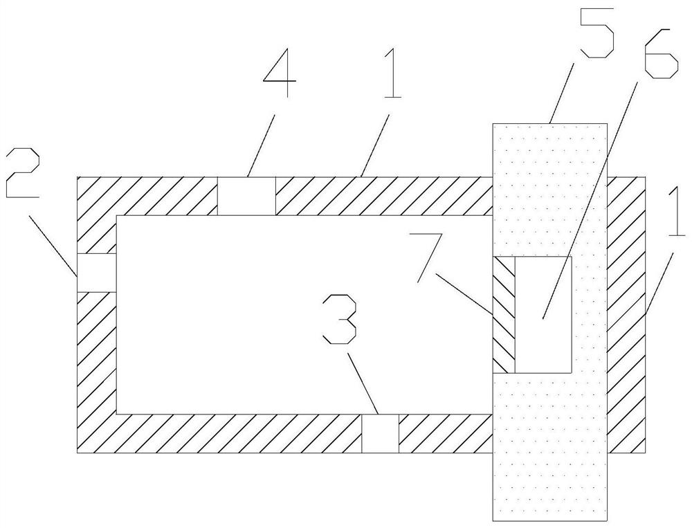
[0021] The invention provides a resonant cavity optical fiber gas sensor, such as figure 1 As shown, it includes a cavity wall 1 , an air inlet 2 , an air outlet 3 , a light transmission hole 4 , a fiber core 5 , a cavity 6 , and a first noble metal layer 7 . The chamber wall 1 encloses a closed chamber, and the chamber wall 1 is made of a dielectric material. The fiber core 5 runs through the chamber. That is, the core 5 penetrates the opposite face of the chamber. exist figure 1 , the core 5 penetrates the top and bottom surfaces of the chamber. Inside the cavity, the surface of the core 5 is provided with a cavity 6 . The cross section of the core 5 is circular. The boundary of the section of the cavity 6 is composed of arcs and line segments. The first noble metal layer 7 is disposed on the top of the cavity 6 , and the first noble metal layer 7 does not completely cover the cavity 6 . The material of the first noble metal layer 7 is gold or silver. The broadband o...
Embodiment 2
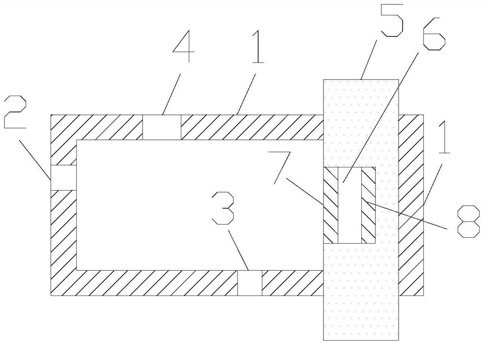
[0025] On the basis of Example 1, such as figure 2 As shown, a second noble metal layer 8 is also included, and the second noble metal layer 8 is disposed at the bottom of the cavity 6 . The material of the second noble metal layer 8 is gold. In this way, the first noble metal layer 7 and the second noble metal layer 8 are placed in the cavity 6, that is, placed in the resonant cavity. Under the action of air flow, the first noble metal layer 7 bends, thereby changing the distance between the first noble metal layer 7 and the second noble metal layer 8 , thereby changing the resonant frequency of the resonant cavity, thereby changing the transmission characteristics of the fiber core 5 . Because surface plasmon polaritons are formed between the first noble metal layer 7 and the second noble metal layer 8, the surface plasmon polaritons significantly depend on the distance between the first noble metal layer 7 and the second noble metal layer 8, Therefore, this design can re...
Embodiment 3
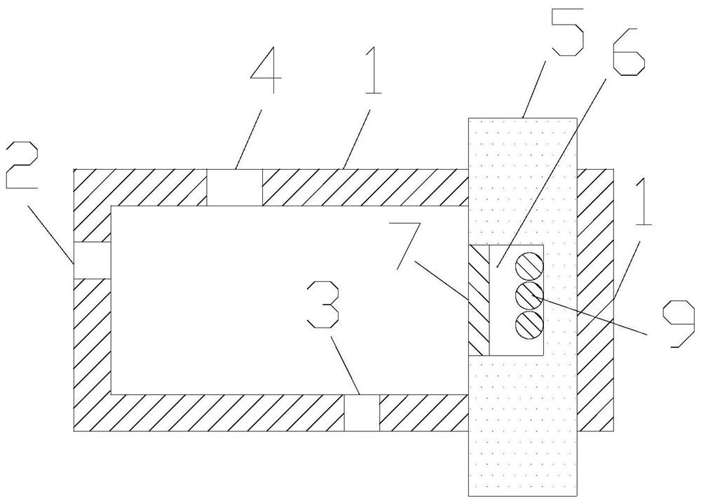
[0028] On the basis of Example 1, such as image 3 As shown, noble metal particles 9 are also included, and the noble metal particles 9 are placed at the bottom of the cavity 6 . The material of noble metal particles 9 is gold. Under laser excitation, surface plasmon resonance is easily formed on the noble metal particle 9 , and the surface plasmon resonance is more significantly dependent on its surrounding environment. Under the action of air flow, the first noble metal layer 7 bends, thereby changing the distance between the first noble metal layer 7 and the noble metal particles 9 , thereby realizing gas detection with higher sensitivity.
[0029] Furthermore, the fiber core 5 is attached to the cavity wall 1, and the cavity 6 faces the cavity. In this way, under the action of the airflow, the fiber core 5 does not move, and only the first noble metal layer 7 is deformed, thereby reducing the influence of the movement of the fiber core 5 on the transmission spectrum and ...
PUM
 Abstract
Description
Claims
Application Information
 - R&D
- Intellectual Property
- Life Sciences
- Materials
- Tech Scout
- Unparalleled Data Quality
- Higher Quality Content
- 60% Fewer Hallucinations
Browse by: Latest US Patents, China's latest patents, Technical Efficacy Thesaurus, Application Domain, Technology Topic, Popular Technical Reports.
© 2025 PatSnap. All rights reserved.Legal|Privacy policy|Modern Slavery Act Transparency Statement|Sitemap|About US| Contact US: help@patsnap.com


