Carbon fiber production method and carbon fiber production equipment capable of realizing one-step demonomerisation and defoaming

A kind of production equipment and technology of carbon fiber, which is applied in the field of carbon fiber production method and equipment field of one-step desingling and degassing, can solve the problems of low production efficiency and poor quality of polymerization liquid, etc. Single-deaeration effect

Pending Publication Date: 2021-05-25
山东永成新材料有限公司
View PDF5 Cites 0 Cited by
  • Summary
  • Abstract
  • Description
  • Claims
  • Application Information

AI Technical Summary

Problems solved by technology

[0010] The present invention aims at the technical problem that single- and degassing needs to be completed in two steps in the existing carbon fiber production process, resulting in poor quality of polymerization liquid and low production efficiency, and provides a method that can greatly reduce the content of monomers in the polymerization liquid and can realize high-load continuous A high-quality, high-efficiency one-step single-step degassing and degassing carbon fiber production method and its equipment for producing and avoiding gel and other quality problems

Method used


Image

  • Carbon fiber production method and carbon fiber production equipment capable of realizing one-step demonomerisation and defoaming

Examples


Embodiment 1

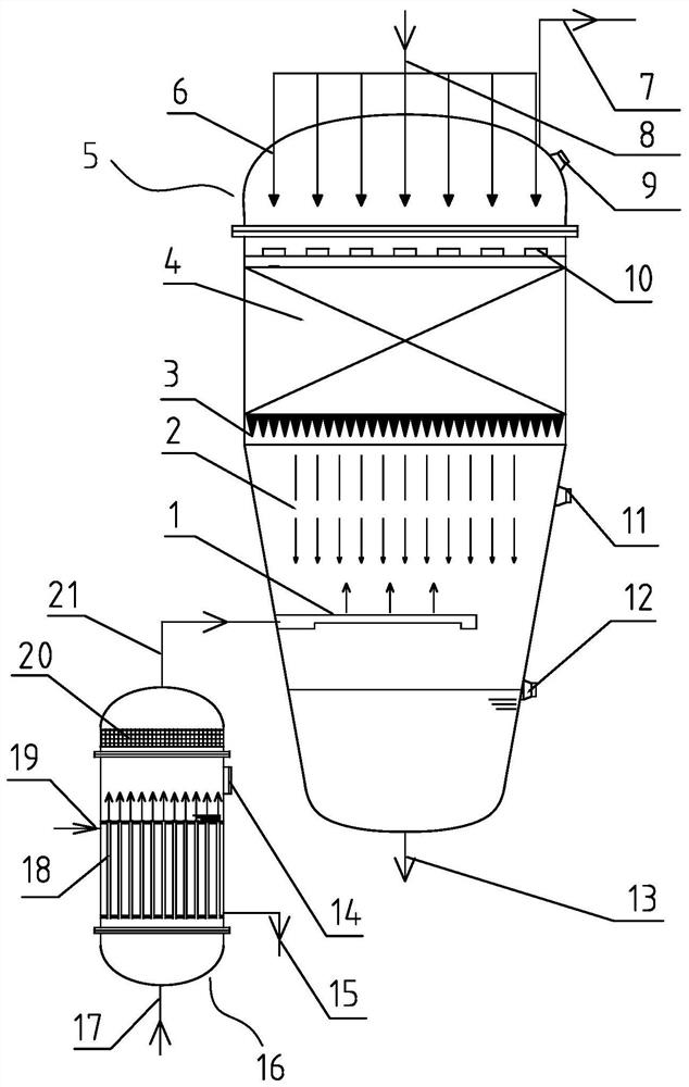
[0035]Such asfigure 1 As shown, a one-step deserted carbon fiber production apparatus includes a reactor 5, a reboiler 16, and a vacuum device, and the vacuum device is connected to the reactor 5 through the vacuum port 7, and the top end of the reactor 5 is provided. The polymer liquid feed pipe 8, the internal feed distribution pipe 6 is provided inside the reactor 5, and the feed distribution tube 6 is connected to the polymer feed pipe 8, and the feed distribution pipe is provided below the feed distribution plate 10, The feed distribution disk 10 is provided with a wire mesh filler 4, and the wire mesh filler 4 is fixed by the stent support, and the wire mesh filler 4 is disposed under the lower circumference 3, and the cone 3 is also fixed. On the bracket. The reactor 5 is provided with a padded DMSO steam dispersing disc 1, and the DMSO steam dispersing disc 1 is located above the liquid portion in the reactor 5 and below the cone 3. Next, a DMSO feed tube 17 is provided belo...

Embodiment 2

[0044]As compared with Example 1, the difference in the present embodiment is that a one-step method of decorating a carbon fiber production method, the specific steps are:

[0045](1) Start the vacuum device to reduce the internal pressure of the reaction kettle 5 until drop to 0.8 kPa;

[0046](2) The polymerization liquid 2 is injected into the feed distribution tube 6 in the reaction kettle 5 by the polymer feed tube 8, and the polymer flow is 3800 kg / hr, the concentration of the monomer is 10%, the polymerization liquid is 12 ~ The 28 feed distribution tube 6 is evenly distributed to the feed distribution tray 10, and from the feed distribution disc 10, the wire mesh filler 4 is passed through the tapered body 3 through the cone 3, and obtains a considerable depreciation- Defoulating massive surface area, and the wire mesh filler 4 is described below, and a fine wire polymerization liquid having a diameter of 0.5 mm to 5 mm is flowed downward; the reaction kettle 5 is provided with...

Embodiment 3

[0051]As compared with Example 1, the difference in the present embodiment is that a one-step method of decorating a carbon fiber production method, the specific steps are:

[0052](1) Start the vacuum device to reduce the internal pressure of the reaction kettle 5 until 5 kPa;

[0053](2) The polymerization liquid 2 is injected into the feed distribution tube 6 in the reaction kettle 5 by the polymer feed tube 8, and the polymer flow is 2300 kg / hr, the concentration of the monomer is 10%, the polymerization liquid is 12 ~ The 28 feed distribution tube 6 is evenly distributed to the feed distribution tray 10, and from the feed distribution disc 10, the wire mesh filler 4 is passed through the tapered body 3 through the cone 3, and obtains a considerable depreciation- Defoulating massive surface area, and the wire mesh filler 4 is described below, and a fine wire polymerization liquid having a diameter of 0.5 mm to 5 mm is flowed downward; the reaction kettle 5 is provided with a top vie...


PUM


Abstract

The invention provides a carbon fiber production method and carbon fiber production equipment capable of realizing one-step demonomerisation and defoaming. The equipment comprises a reaction kettle, a reboiler and a vacuumizing device, wherein the vacuumizing device is connected with the reaction kettle; a polymerization liquid feeding pipe is arranged at the top end of the reaction kettle; a feeding distribution pipe is arranged in the reaction kettle; a feeding distribution disc is arranged below the feeding distribution pipe; a filler is arranged below the feeding distribution disc; a flow dividing device is arranged below the filler; a DMSO steam dispersing disc is arranged in the reaction kettle; a DMSO feeding pipe is arranged below the reboiler; a DMSO feeding dispersing pipe is arranged in the reboiler; a steam inlet is formed in the reboiler; a demister is arranged in the reboiler; and a DMSO steam pipe is arranged between the reboiler and the reaction kettle. According to the invention, the technical problems that the quality of a polymerization solution is poor, and the production efficiency is low since demonomerisation and defoaming need to be completed in two steps in an existing carbon fiber production process are solved. The carbon fiber production method and the carbon fiber production equipment in the invention can be widely applied to a demonomerisation and defoaming process of carbon fibers.

Description

Technical field[0001]The present invention relates to a carbon fiber production method and apparatus, in particular, to a carbon fiber production method and equipment therefor a one-step manifold.Background technique[0002]During domestic carbon fiber production, the aggregation process is detached, and the debon is generally operated by two steps. The polymerization process produced by DMSO as the solvent produced, low conversion, and an AN monomer containing about 10% to 10%, and the residual monomer AN is removed twice under vacuum to allow the polymerization. The monomer residue is reduced to 100 to 300 ppm, which is a spinning polymer.[0003]In addition, bubbles are generated during the polymerization reaction, and the bubbles are not easy to remove, and the residual bubbles can cause broken wire, affect the mass of carbon fibers, so the polymerization fluid must also be deprived.[0004]In China, many companies in China in order to increase the deciding of the polymer stock soluti...

Claims


Application Information

Patent Timeline
Patent Type & Authority Applications(China)
IPC IPC(8): C08F20/44C08F2/00C08F2/01D01F9/22B01J3/04B01J3/03B01J3/02B01D19/04B01D3/06
CPCC08F20/44C08F2/00C08F2/01D01F9/22B01J3/006B01J3/03B01J3/02B01J3/002B01D19/0422B01D3/06
Inventor 刘运波张立坚赵彦国潘林武周占发张伟王恩波杨昆孙毅沈传石
Owner 山东永成新材料有限公司
Why Eureka
Try Eureka