Eureka AIR delivers breakthrough ideas for toughest innovation challenges, trusted by R&D personnel around the world.

Corrosion hole forming device for high-voltage aluminum electrolysis electronic aluminum foil

An electronic aluminum foil and aluminum electrolysis technology, which is applied in the electrolysis process and electrolysis components, etc., can solve the problems affecting the uniformity of the distribution of pores, the uniformity of the hole depth, the effect of the corrosion effect of the pores on the upper end of the aluminum foil, and the inability to effectively discharge air bubbles. The uniformity of the hair hole, the reduction of installation costs, and the effect of reducing vibration

Pending Publication Date: 2021-05-28
GUANGXI HEZHOU GUIDONG ELECTRONICS TECH
View PDF2 Cites 0 Cited by
  • Summary
  • Abstract
  • Description
  • Claims
  • Application Information

AI Technical Summary

Problems solved by technology

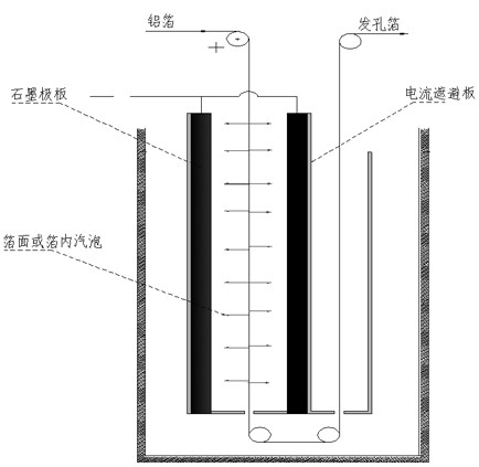
The bubbles generated in the holes during the traditional hole making process are difficult to discharge, and the bubbles trapped on the surface of the aluminum foil will not only affect the uniformity of the hole distribution and the consistency of the hole depth, but also cause hydrogen embrittlement, which will affect the finished product. Properties of electronic aluminum foil
Secondly, in the traditional electrolytic corrosion process, a large number of bubbles will be generated in the corrosion tank, and the upwelling of the bubbles will cause the liquid level to fluctuate, which will affect the corrosion effect of the upper end of the aluminum foil.
[0005] The patent No. CN201920698669.0 discloses a high-pressure corrosion foil reaction tank reaction bubble screening device. The device has a certain screening effect on a large amount of generated gas, but there are still a large number of bubbles accumulated on the upper end of the aluminum foil, which will cause liquid surface fluctuations
The patent No. ZL201711486915.8 discloses a power-on electrode device for aluminum foil electrolysis. control, but can not effectively discharge the air bubbles in the hole

Method used


Image

  • Corrosion hole forming device for high-voltage aluminum electrolysis electronic aluminum foil
  • Corrosion hole forming device for high-voltage aluminum electrolysis electronic aluminum foil
  • Corrosion hole forming device for high-voltage aluminum electrolysis electronic aluminum foil

Examples


Embodiment 1

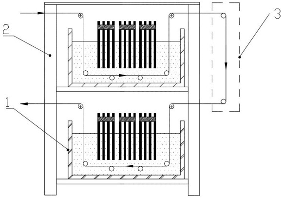
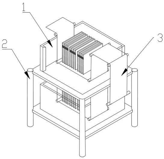
[0034] A corroding perforation device for high-voltage aluminum electrolytic electronic aluminum foil, including two primary perforation slots 1, a bracket 2 and a flipping device 3;

[0035] The support 2 is divided into two layers, and each layer is equipped with a primary hair hole groove 1, and a turning device 3 is provided on the side of the support 2; the turning device 3 includes a transmission roller I8 and a transmission roller II9 , the transmission roller I8 is located above the transmission roller II9;

[0036] The primary hair cell 1 includes an electrolyte tank body 4, and the middle part of the electrolyte tank body 4 is provided with 3 groups of graphite pole plate groups 5 vertically downward, and each group of graphite pole plate groups 5 is connected to a high-frequency The negative pole of the switching power supply; the graphite pole plate group 5 includes copper bars 11 and 4 graphite pole plates 10, the graphite pole plates 10 are parallel to each other...

Embodiment 2

[0040]The difference between this embodiment and Embodiment 1 is that: the electrolyte tank body 4 is provided with 2 sets of graphite pole plate groups 5; the graphite pole plate group 5 has 2 graphite pole plates 10, graphite The distance between the pole plates 10 is 20mm; the height of the graphite pole plate group 5 is 400mm. A ceramic roller 7 is arranged below the graphite electrode plate group 5 . When the aluminum foil passes through the bottom surface of each graphite pole plate group 5 to corrode and open holes, the lower part of the aluminum foil is supported by a ceramic copper roller 7 .

[0041] The working principle of this embodiment is the same as that of Embodiment 1.

Embodiment 3

[0043] The difference between this embodiment and Embodiment 1 is that: the electrolyte tank body 4 is provided with 4 groups of graphite pole plate groups 5; there are 8 graphite pole plates 10 in the graphite pole plate group 5, graphite The distance between the pole plates 10 is 100mm; the height of the graphite pole plate group 5 is 1000mm. Two ceramic rollers 7 are arranged below the graphite plate group 5 . When the aluminum foil passes through the bottom surface of each graphite pole plate group 5 to corrode and open holes, the lower part of the aluminum foil is supported by a ceramic copper roller 7 .

[0044] The working principle of this embodiment is the same as that of Embodiment 1.


PUM

PropertyMeasurementUnit
Heightaaaaaaaaaa
Heightaaaaaaaaaa

Abstract

The invention discloses a corrosion hole forming device for high-voltage aluminum electrolysis electronic aluminum foil. The corrosion hole forming device comprises two primary hole forming grooves, a support and a turn-over device. The support is divided into two layers, each layer is provided with one corresponding primary hole forming groove, and the turn-over device is arranged on the side face of the support. Each primary hole forming groove comprises an electrolyte tank body, at least two graphite pole plate sets which are vertically downward are arranged in each electrolyte tank body, and each graphite pole plate set is connected with a high-frequency switching power supply. Rollers used for guiding the aluminum foil to advance are also arranged in the electrolyte tank bodies. When the device is used for corrosion hole forming, the hole forming face of the aluminum foil is parallel to the bottom faces of the primary hole forming grooves, and therefore bubbles generated on the foil face and in holes of the aluminum foil during hole forming corrosion can be effectively discharged, accumulation of a large number of bubbles at the upper end of the aluminum foil can be avoided, finally, the hole forming distribution uniformity is improved, the hole diameter of the corrosion foil is increased, and therefore the capacity of the corrosion foil is improved.

Description

technical field [0001] The invention relates to the technical field of anode foil corrosion for aluminum electrolytic capacitors, in particular to a device for corroding and generating holes in high-voltage aluminum electrolytic electronic aluminum foil. Background technique [0002] High-capacity miniaturization is the development trend of aluminum electrolytic capacitors. Studies have shown that electrolytic etching of high-purity aluminum foil with {100} texture to expand its specific surface area and increase specific capacitance is the most effective technical approach for the miniaturization of aluminum electrolytic capacitors. [0003] The electrolytic corrosion process of high-voltage anode foil generally includes seven main steps: pre-treatment, porosity corrosion, intermediate treatment 1, hole expansion corrosion 1, intermediate treatment 2, hole expansion corrosion 2, and post-treatment (chemical cleaning). Among them, intermediate treatment and hole expansion c...

Claims


Application Information

Patent Timeline
IPC IPC(8): C25F3/04C25F7/00
CPCC25F3/04C25F7/00
Inventor 杨小飞熊传勇梁力勃蔡小宇蒋碧君
Owner GUANGXI HEZHOU GUIDONG ELECTRONICS TECH
Why Eureka
Eureka Blog
Learn More