Prefabricated concrete frame system with exposed flat grid floor slabs and exposed truss girders

A frame system and truss beam technology, applied to truss structures, truss beams, floor slabs, etc., can solve the problems of complex installation, increased construction period and cost, and the need to improve the construction technology of prefabricated buildings, so as to reduce cost and increase construction Speed, the effect of reducing plate thickness

Inactive Publication Date: 2021-05-28
CHONGQING UNIV
View PDF6 Cites 3 Cited by
  • Summary
  • Abstract
  • Description
  • Claims
  • Application Information

AI Technical Summary

Problems solved by technology

The on-site assembly and installation of prefabricated columns, composite beams and composite floors is energy-saving and environmentally friendly, which is in line with the development trend of prefabricated at this stage. However, when the prefabricated beams and prefabricated floors are hoisted to the construction site, the traditional scaffolding support system is still required, which is complicated to install and increases the construction period. and cost, the construction technology of prefabricated buildings still needs to be improved

Method used


Image

  • Prefabricated concrete frame system with exposed flat grid floor slabs and exposed truss girders
  • Prefabricated concrete frame system with exposed flat grid floor slabs and exposed truss girders
  • Prefabricated concrete frame system with exposed flat grid floor slabs and exposed truss girders

Examples


Embodiment 1

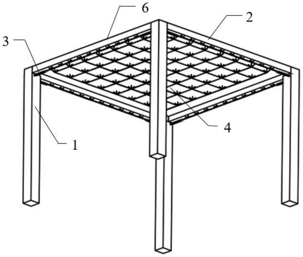
[0042] This example discloses a prefabricated concrete frame system with exposed flat grid floor and exposed truss beams, see figure 1 , including prefabricated concrete columns 1, exposed truss composite beams 2, energy dissipation dampers 3, exposed flat grid frame composite slab bottom plates 4 and post-cast concrete layers 6.

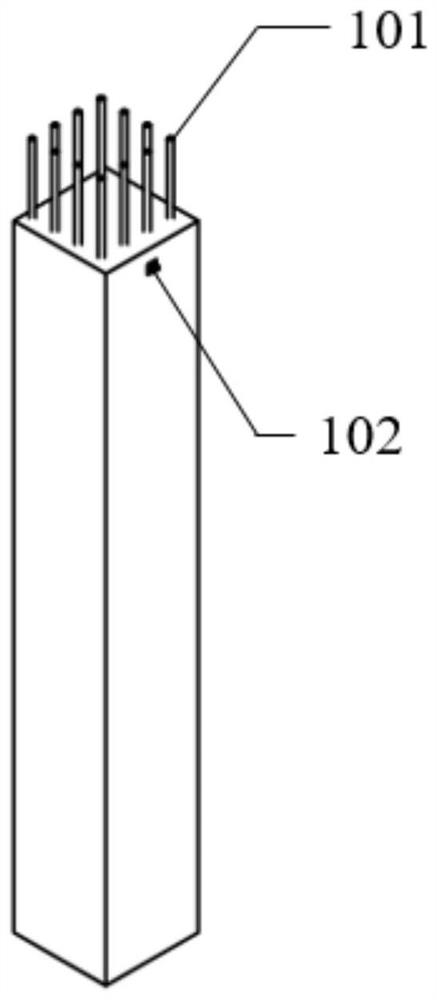
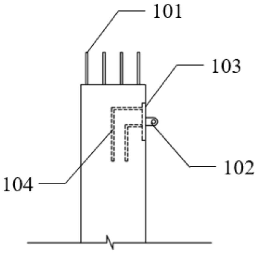
[0043] see figure 2 , 3 , the precast concrete column 1 includes column longitudinal reinforcement 101, column ear plate 102, conversion steel plate 103 and anchoring reinforcement 104; column longitudinal reinforcement 101 is arranged inside the precast concrete column 1, and the reinforcement is drawn out along the column; conversion steel plate 103 is pre-embedded in the precast concrete column 1. The column ear plate 102 and the anchoring steel bar 104 are welded with the conversion steel plate 103, the column ear plate 102 is exposed on the column surface, and the anchoring steel bar 104 is pre-embedded in the precast concrete column 1.

[0...

Embodiment 2

[0050] The main structure of this embodiment is the same as that of Embodiment 1, see Figure 11 , wherein the precast concrete column 1 is a corner column, and the upper chord 2031 of the space truss is bent.


PUM


Abstract

The invention discloses a prefabricated concrete frame system with exposed flat grid floor slabs and exposed truss girders, and belongs to the technical field of constructional engineering. The prefabricated concrete frame system comprises a prefabricated concrete column, an exposed truss superposed beam, an energy dissipation damper, an exposed flat grid composite slab bottom plate, a temporary support and a post-cast concrete layer, wherein a space truss is exposed out of the superposed beam, and the exposed truss is connected with the prefabricated concrete column through the energy dissipation damper; and a flat grid is exposed out of the bottom of a composite slab, the composite slab is placed on the temporary support, and the purpose of few supports is achieved. According to the prefabricated concrete frame system disclosed by the invention, the space truss and the flat grid are exposed, so that the beam height and the plate thickness are reduced, and the manufacturing cost is reduced; and the temporary support is placed on the space truss, so that the number of the supports is reduced, and the construction speed is increased.

Description

technical field [0001] The invention relates to an assembled frame structure system and belongs to the technical field of construction engineering. Background technique [0002] With the development of national industrialization and urbanization, the construction industry has become a pillar industry of my country's economy, but the traditional construction industry has problems such as heavy pollution, slow construction progress and high resource consumption that hinder the sustainable development of the construction industry. The construction industry urgently needs to promote a A new model of construction. The development of prefabricated buildings meets the requirements of green buildings, and has become a hot spot in the construction industry with the advantages of high precision, fast construction and high quality. Prefabricated building planning has been issued intensively since 2015, and the "Industrialized Building Evaluation Standard" was released at the end of 201...

Claims


Application Information

Patent Timeline
Patent Type & Authority Applications(China)
IPC IPC(8): E04B1/20E04B1/21E04C3/20E04B5/17E04B1/38E04B1/58E04B1/98E04H9/02
CPCE04B1/20E04B1/21E04C3/20E04B5/17E04B1/58E04B1/98E04H9/021E04B1/388
Inventor 白久林梁媛陈辉明胡少伟杨经纬金双双
Owner CHONGQING UNIV
Why Eureka
Try Eureka