
Welding wire rod, manufacturing method thereof and welding method of welding wire rod and PCB

A welding method and manufacturing method technology, applied in the directions of printed circuit manufacturing, cable/conductor manufacturing, conductive core components, etc., can solve the problems of reduced production efficiency, high welding strength, increased cost, etc., to reduce labor intensity, High weld strength and the effect of improving weld strength

Active Publication Date: 2021-05-28
株洲菲斯罗克光电科技股份有限公司
View PDF10 Cites 0 Cited by
  • Summary
  • Abstract
  • Description
  • Claims
  • Application Information

AI Technical Summary

Problems solved by technology

In order to ensure the welding strength, a section of the exposed welding part passing through the welding hole usually needs a certain length. Because the hardness of the conductive core is high and it is not easy to deform, it must be covered with a layer of welding material after wave soldering, resulting in the exposed welding part and its The welding part formed by the external covering welding material has a high protrusion height on the surface of the plate, which is easy to cause short circuit and other problems. Therefore, it is usually necessary to cut off a part of the welding part by manual shearing to reduce the protrusion height, which not only leads to production efficiency reduce the cost, increase the cost, and also reduce the welding strength between the exposed welding part and the plate, making it difficult to ensure welding reliability
At present, there is no welding technology that meets the requirements of high welding strength and low bump height with only one welding

Method used


Image

  • Welding wire rod, manufacturing method thereof and welding method of welding wire rod and PCB
  • Welding wire rod, manufacturing method thereof and welding method of welding wire rod and PCB
  • Welding wire rod, manufacturing method thereof and welding method of welding wire rod and PCB

Examples


Embodiment 1

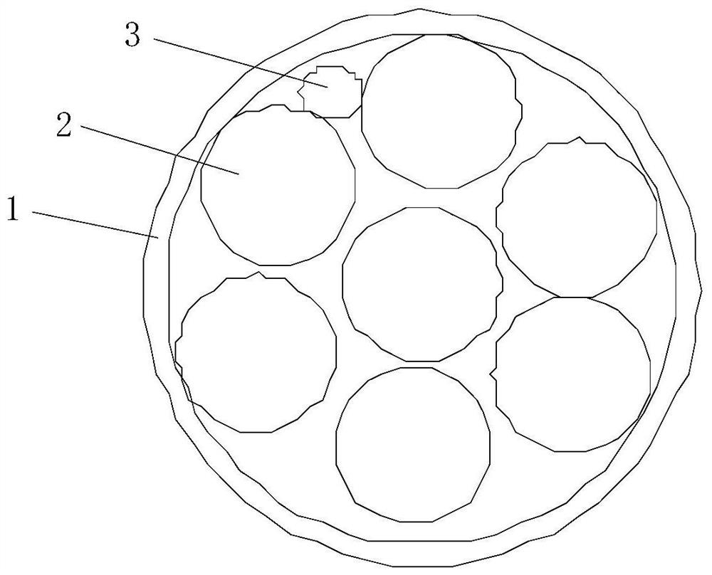
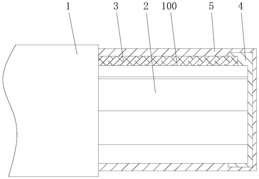
[0029] like figure 1 As shown, the welding wire of this embodiment includes an insulating sleeve 1 and a plurality of conductive cores 2 pierced in the insulating sleeve 1, and a heat-shrinkable fiber strip 3 is also worn in the insulating sleeve 1, and the conductive core 2 and The heat-shrinkable fiber strip 3 protrudes from one end of the insulating sleeve 1 to form an exposed welding part 100, and the exposed welding part 100 is divided into a middle section and an end section connected in sequence along the direction extending from the insulating sleeve 1, and the outer part of the end section The cladding is connected with the first cladding layer 4 formed by the first welding material, the first cladding layer 4 connects the conductive core 2 and the heat-shrinkable fiber strip 3 as a whole, and the conductive core 2 is connected in the first cladding layer 4. In the case of being connected with the heat-shrinkable fiber strip 3 as a whole, when the heat-shrinkable fibe...

Embodiment 2

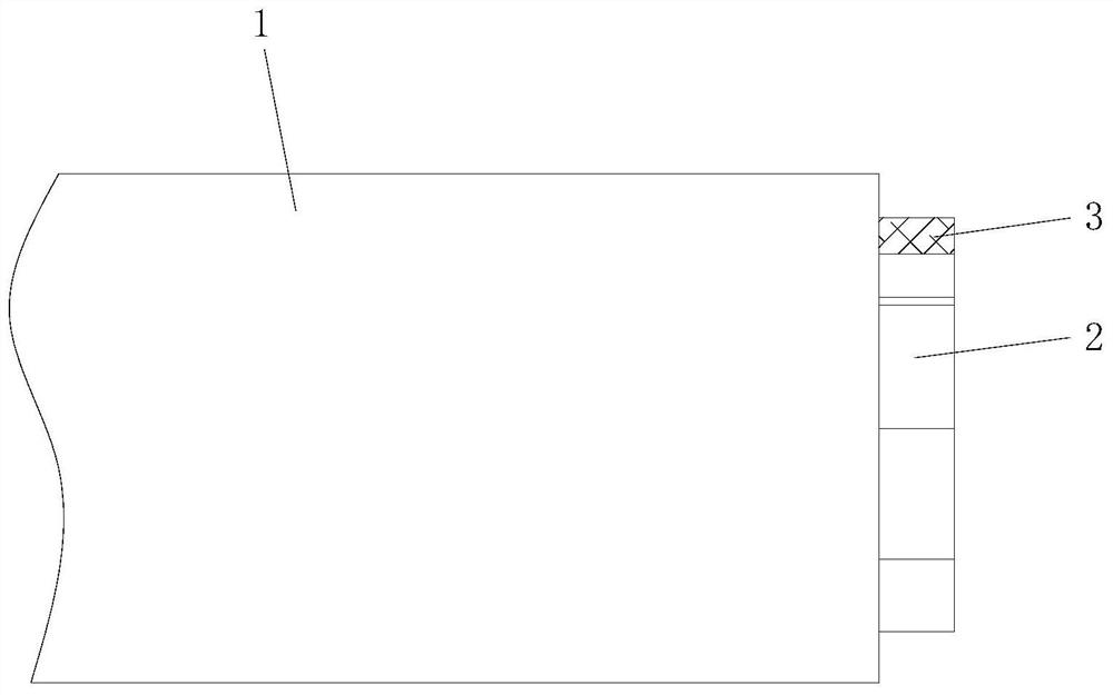
[0037] A method for manufacturing welding wires in Example 1, specifically, prefabricating a cable with a conductive core 2 and a heat-shrinkable fiber strip 3 in an insulating sleeve 1 (see image 3 ), first peel off a section of insulating sleeve 1 at one end of the cable to expose the end section of the exposed welding part 100, and coat and attach the first welding material to the outside of the conductive core 2 and the heat-shrinkable fiber strip 3 exposed at the end section Form the first cladding layer 4 (see Figure 4 ); Then, continue to strip off a section of insulating sleeve 1 so that the middle section of the exposed weld 100 is exposed (see Figure 5 ), the second welding material is coated and attached to the conductive core 2 and the heat-shrinkable fiber strip 3 of the middle section and the outside of the first cladding layer 4 to form the second cladding layer 5 (see figure 2 ). In the manufacturing method, a section of the insulating sleeve 1 is first s...

Embodiment 3

[0040] A welding method for welding the wire rod and the PCB board in Embodiment 1, the welding method is specifically, the end of the welding wire rod with the second cladding layer 5 is penetrated into the welding hole arranged on the PCB board body 6, and wave soldering is used The welding method is to weld and fix the welding wire rod and the PCB board body 6. The welding material used in wave soldering is the third welding material, and the melting point temperature of the third welding material is greater than the melting point temperature of the second welding material and the thermal shrinkage of the heat shrinkable fiber strip 3 The larger one of the deformation temperature, and the melting point temperature of the third welding material is lower than the melting point temperature of the first welding material. This welding method can make the first cladding layer 4 formed by the first welding material not melt and keep cladding and connecting the conductive core 2 and...


PUM

PropertyMeasurementUnit
melting pointaaaaaaaaaa

Abstract

The invention discloses a welding wire rod, a manufacturing method thereof and a welding method of the welding wire rod and a PCB. The welding wire rod comprises an insulating sleeve, a plurality of conductive cores and heat-shrinkable fiber strips, wherein one end of each conductive core and one end of each heat-shrinkable fiber strip extend out to form an exposed welding part, and the exposed welding part is divided into a middle section and an end section; the end section is connected with a first wrapping layer formed by a first welding material in a wrapping mode, the middle section and the first wrapping layer are connected with a second wrapping layer formed by a second welding material in a wrapping mode, and the heat-shrinkable deformation temperature of the heat-shrinkable fiber strip and the melting point temperature of the second welding material are both smaller than the melting point temperature of the first welding material. The manufacturing method comprises the following steps of firstly, stripping a section of insulating sleeve and manufacturing the first wrapping layer, and then stripping a section of insulating sleeve and manufacturing the second wrapping layer. According to the welding method, the welding wire and the PCB body are welded and fixed through a wave soldering method. Manual shearing is not needed after welding, the labor intensity of workers can be reduced, labor is saved, and meanwhile the welding portion has high welding strength and low protruding height.

Description

technical field [0001] The invention relates to the field of welding technology, in particular to a welding wire, its manufacturing method and its welding method with a PCB board. Background technique [0002] When welding wires to PCB boards and other boards, in order to ensure the connection reliability and reduce the overall thickness, the wires and boards are usually welded by wave soldering. The tube is stripped to expose the conductive core (usually copper core) as the exposed welding part, and after the exposed welding part passes through the welding hole on the plate, wave soldering is carried out by wave soldering equipment, so that the exposed welding part passes through the welding hole One section is welded and fixed with the plate. In order to ensure the welding strength, the section where the exposed welding part passes through the welding hole usually needs a certain length. Since the hardness of the conductive core is high and it is not easy to deform, it mu...

Claims


Application Information

Patent Timeline
Patent Type & Authority Applications(China)
IPC IPC(8): H01B7/02H01B7/00H01B13/22H05K3/34
CPCH01B7/02H01B7/0009H01B13/22H05K3/3447
Inventor 李慧鹏王已熏易军
Owner 株洲菲斯罗克光电科技股份有限公司
Learn More