
A visual monitoring system and method

A monitoring and video information technology, applied in the field of visual monitoring system, can solve the problems of inability to guarantee measurement accuracy, difficult distance measurement, recognition accuracy and accuracy rate, etc., to improve recognition accuracy and recognition efficiency, and ensure correctness , the effect of improving reliability

Active Publication Date: 2022-07-05
SHANDONG LUNENG SOFTWARE TECH
View PDF16 Cites 0 Cited by
  • Summary
  • Abstract
  • Description
  • Claims
  • Application Information

AI Technical Summary

Problems solved by technology

[0005] (1) The visual monitoring equipment installed on the tower of the transmission line may encounter different meteorological environments, such as long-term rainy weather in the southern Meiyu season, foggy weather in the Sichuan Basin, rainy and snowy weather in winter in the Northeast, and low sunshine The inspection quality of the system in bad weather has attracted more and more attention from users, especially the weather with low visibility has seriously affected the recognition accuracy and accuracy of the system.
[0006] (2) The visual monitoring system needs to use a binocular camera to measure the distance of the target object, but based on cost considerations, it will not cover a large area and install a binocular camera. Most places use a monocular camera, so it is difficult to use only a monocular camera. The accuracy of the distance measurement cannot be guaranteed
[0007] (3) During the upgrade process of the visual surveillance system, due to the absence of a feedback mechanism, the background cannot accurately know whether the visualization device has been successfully upgraded; especially in the absence of an operation interface, the user cannot directly observe the upgrade result, resulting in the inability to correctly judge the visualization Whether the device is successfully upgraded; thus affecting the stable and reliable operation of the visualization system
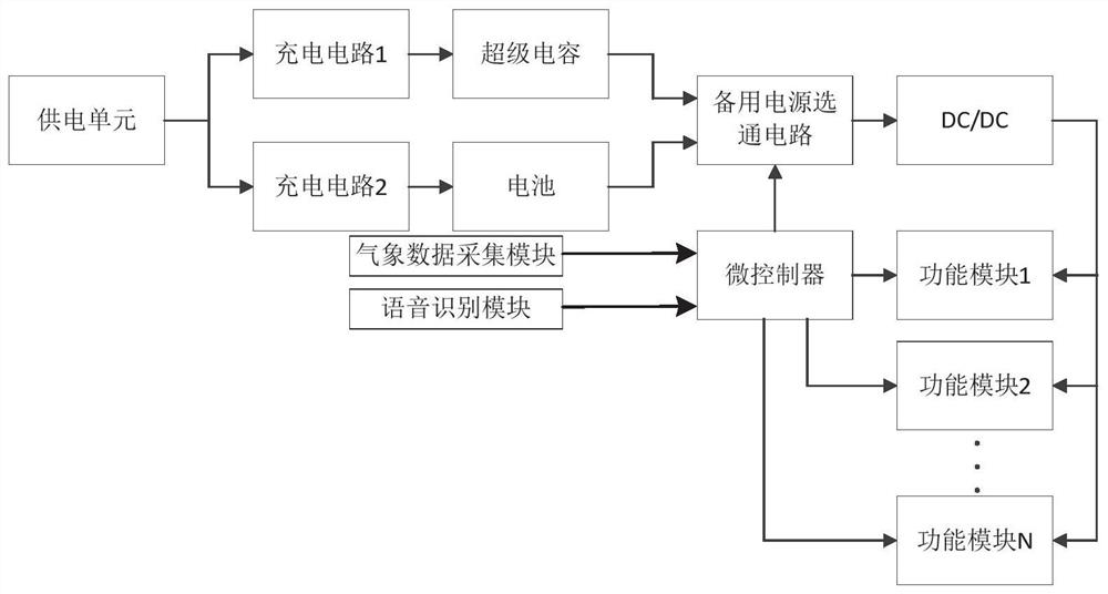
The battery voltage is relatively stable. For example, the working voltage of a 6.4V lithium iron phosphate battery is 5.5V to 7.2V, while the working voltage range of a super capacitor is wide, up to 0 to 10.8V. In the existing hybrid power supply of batteries and super capacitors, The battery and the supercapacitor are connected in parallel through a diode, and supply power to the subsequent load according to the voltage level. When the discharge voltage of the supercapacitor reaches or is lower than the battery voltage, the system takes power from the battery. In this way, the remaining power of the supercapacitor cannot be released, and the supercapacitor is not fully utilized. Capacitor capacity
[0009] (5) The existing research on the power supply strategy of the visual monitoring system often focuses on the balanced control of power supply and power supply load, and the research on the control of the power supply strategy of the visual monitoring system based on meteorological data is relatively rare

Method used

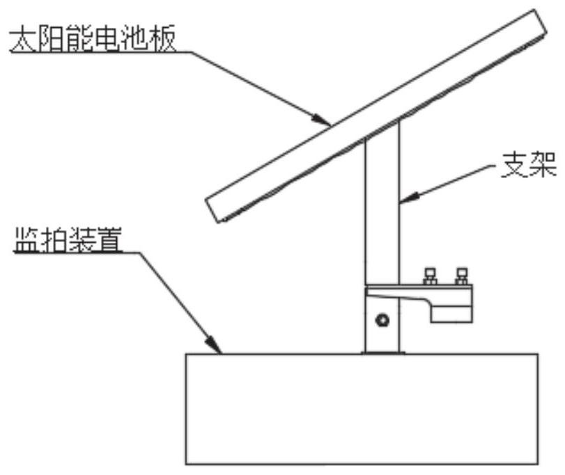
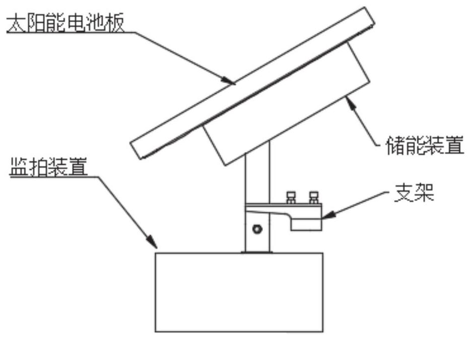

Image

  • A visual monitoring system and method
  • A visual monitoring system and method
  • A visual monitoring system and method

Examples


Embodiment 1

[0052] In one or more embodiments, a visual monitoring system for overhead lines is disclosed, including: a visual monitoring device, a power supply module and a microcontroller; the visual monitoring device follows a set rule (for example, how long the interval is Collecting information once) to collect overhead line images or video information, and to perform front-end processing on the collected images or video information; the power supply module is connected to the visual monitoring device and the microcontroller respectively; the microcontroller is based on the current power of the power supply module. Select different power supply strategies to supply power to each functional module of the visual monitoring device.

[0053] As an optional embodiment, the visual monitoring device is divided into several functional modules according to the realized functions, including: an image acquisition and processing module, a background 4G communication module, a sound and light alar...

Embodiment 2

[0189] In one or more embodiments, a tunnel cable visual monitoring system is disclosed, including: a visual monitoring device, a power supply module and a microcontroller; the visual monitoring device follows a set rule (for example, how long the interval is) Collecting information once) collects image or video information in the tunnel cable, and can perform front-end processing on the collected image or video information; the specific data processing process is implemented by the method disclosed in the first embodiment.

[0190] The power supply module is connected to the visual monitoring device and the microcontroller respectively; the microcontroller selects different power supply strategies to supply power to each functional module of the visual monitoring device according to the current power of the power supply module.

[0191] The visual monitoring device may adopt the structure of the visual monitoring device disclosed in the first embodiment, and details are not re...

Embodiment 3

[0200] In one or more embodiments, a visual monitoring system for transmission lines is disclosed. The visual monitoring system in Embodiment 1 is set on the transmission line to realize visual monitoring and early warning of the transmission line.


PUM


Abstract

The invention discloses a visual monitoring system and method, comprising: a visual monitoring device, a power supply module and a microcontroller; the visual monitoring device collects transmission line images or video information according to set rules, and can monitor the collected The image or video information is processed at the front end; the power supply module is connected to the visual monitoring device and the microcontroller respectively; the microcontroller selects different power supply strategies to supply power to the visual monitoring device according to the current power of the power supply module. The invention proposes a method for measuring the distance of a hidden object in haze weather with a monocular camera, which uses a combination of dark channel prior technology and artificial intelligence recognition technology to process, convert and extract images collected in haze weather, and measure the distance of the target object. It solves the problem of measuring the distance of hidden dangers in haze days, and realizes automatic identification of hidden danger sources and calculation of the distance of hidden danger sources in haze days.

Description

technical field [0001] The invention belongs to the technical field of power transmission line monitoring, and in particular relates to a visual monitoring system and method. Background technique [0002] The statements in this section merely provide background information related to the present disclosure and do not necessarily constitute prior art. [0003] At present, the transmission lines of the power system are usually distributed in a linear shape, which has spatial distribution characteristics such as long distances and an open operating environment with scattered poles and towers. There are more complex problems in the detection of transmission lines, such as the difficulty of detection due to the large span of transmission lines. The increase, and the complex surrounding environment of the transmission line lead to greater interference to the detection. It is very important to monitor and manage UHV transmission lines safely and effectively to ensure the safe oper...

Claims


Application Information

Patent Timeline
Patent Type & Authority Patents(China)
IPC IPC(8): H02G1/02H04N7/18
CPCH02G1/02H04N7/181Y04S10/40
Inventor 刘强冯飞冯鑫李巨宁傅晓姜涛张年文焦之明巩方波纪洪伟
Owner SHANDONG LUNENG SOFTWARE TECH
Learn More