Laser cutting machine with automatic positioning function

A laser cutting machine, automatic positioning technology, used in laser welding equipment, welding/cutting auxiliary equipment, manufacturing tools, etc., can solve the problems of unable to fix products, waste materials, pollute the environment, etc., to improve the cutting effect and improve the cutting efficiency. , the use of excellent effect

Inactive Publication Date: 2021-06-01
张荷友
View PDF1 Cites 6 Cited by
  • Summary
  • Abstract
  • Description
  • Claims
  • Application Information

AI Technical Summary

Problems solved by technology

[0003] A Chinese utility model patent with publication number CN202212696U discloses a laser cutting machine. The laser cutting machine includes a frame body, slide rails, a laser generator, a worktable and two guide rails. Two bases are fixedly installed, and the two guide rails are fixedly installed on the upper end surfaces of the two bases. The worktable is carried on the main body of the frame and is located between the two guide rails. The laser generator is slidably installed on the slide rails, and the two ends of the slide rails slide respectively. Installed on the two guide rails to drive the laser generator to slide on the guide rails. There are also several adjustment knobs installed on the main body of the frame. The adjustment knobs are in contact with the lower end surface of the worktable, and the height and horizontal position of the worktable can be adjusted as required. , the adjustment is convenient and the operation is simple, and the cutting accuracy is improved, but in the actual use process, the product cannot be effectively fixed, and more smoke will be generated during the cutting process, and it is difficult to quickly discharge and purify the smoke. It pollutes the environment, and the waste heat generated during the cutting process will expand the cutting edge, waste materials, and even produce unevenness, which needs to be improved

Method used


Image

  • Laser cutting machine with automatic positioning function
  • Laser cutting machine with automatic positioning function
  • Laser cutting machine with automatic positioning function

Examples


Embodiment Construction

[0037]In order to make the object, technical solution and advantages of the present invention clearer, the present invention will be further described in detail below in combination with specific embodiments and with reference to the accompanying drawings. It should be understood that these descriptions are exemplary only, and are not intended to limit the scope of the present invention. Also, in the following description, descriptions of well-known structures and techniques are omitted to avoid unnecessarily obscuring the concept of the present invention.

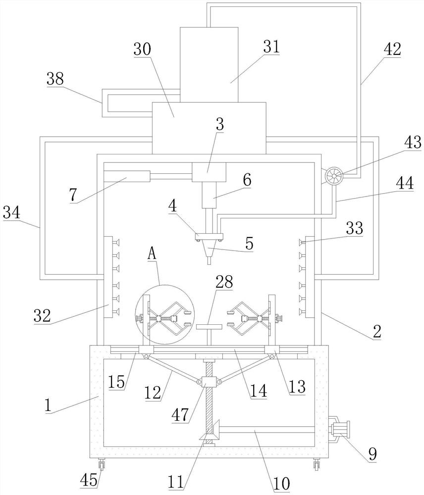
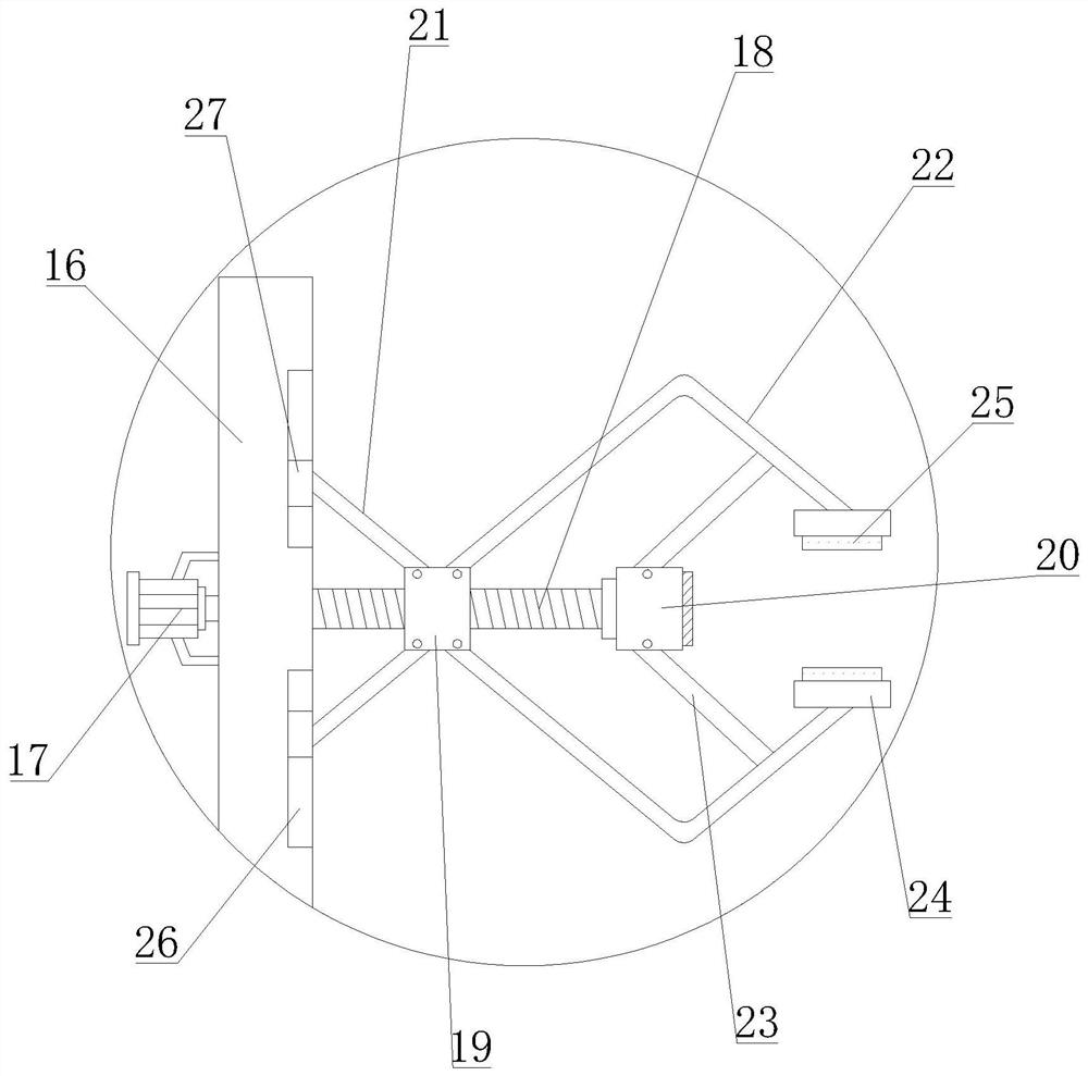
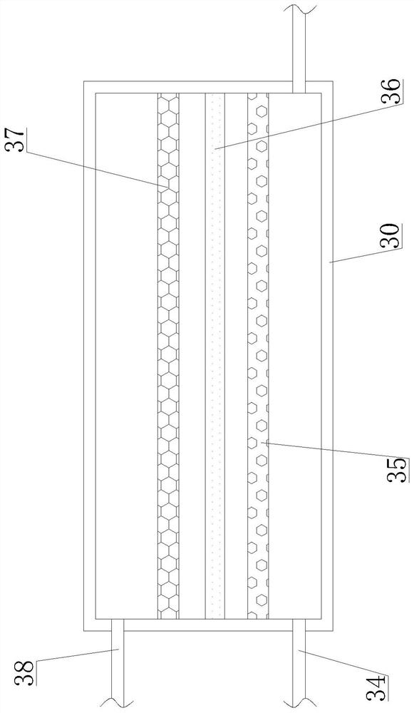
[0038] Such as Figure 1-7 As shown, a laser cutting machine with automatic positioning function proposed by the present invention includes a fixed box 1, a protective box 2, a movable part 3, a gas distribution plate 4, a laser cutting head 5, a stud 11, and a first rotating part 12 , vertical plate 16, screw rod 18, moving block 19, second rotating part 21, L-shaped part 22, connecting part 23, purification box 30, cool...


PUM


Abstract

The invention relates to a laser cutting machine with an automatic positioning function. The laser cutting machine with the automatic positioning function comprises a fixing box, a protective box, a purifying box and a cooling box; the protective box is arranged on the fixing box; a gas distributing disc is arranged at the bottom of a Z-axis telescopic rod, and a laser cutting head is arranged on the gas distributing disc; gas collecting cases are arranged in the protective box, flue gas sucking covers are arranged on the gas collecting cases, and first connection pipes communicate with the gas collecting cases and the purifying box; a first connection case and a second connection case are arranged in the cooling box, and the second connection case is located over the first connection case; a second connection pipe communicates with the purifying box and the first connection case, and a heat-dissipating pipe communicates with the first connection case and the second connection case; a gas return pipe and an exhausting hose are arranged on a gas pump, and the gas return pipe communicates with the second connection case; and gas spraying heads are arranged at the bottom of the gas distributing disc, and the exhausting hose communicates with the gas distributing disc. According to the laser cutting machine with the automatic positioning function, not only can products be effectively fixed, but also flue gas generated in cutting processes can be purified, and product cuts can be cooled, so that functions are diverse, and the laser cutting machine with the automatic positioning function has an excellent use effect.

Description

technical field [0001] The invention relates to the technical field of laser cutting machines, in particular to a laser cutting machine with an automatic positioning function. Background technique [0002] The laser cutting machine focuses the laser emitted from the laser into a high-power-density laser beam through the optical path system. The laser beam irradiates the surface of the workpiece to make the workpiece reach the melting point or boiling point. As the relative position of the beam and the workpiece moves, the final Make the material form a slit, so as to achieve the purpose of cutting; laser cutting process replaces the traditional mechanical knife with an invisible beam, with high precision, fast cutting, not limited to the limitation of cutting pattern, automatic typesetting saves material, smooth incision, Low processing cost and other characteristics will gradually improve or replace traditional metal cutting equipment; the mechanical part of the laser cutte...

Claims


Application Information

Patent Timeline
Patent Type & Authority Applications(China)
IPC IPC(8): B23K26/38B23K26/70B23K37/04B23K26/142B01D46/12B01D53/04
CPCB01D46/12B01D53/04B23K26/38B23K37/0435B23K26/142B23K26/702B23K26/703
Inventor 张荷友
Owner 张荷友
Why Eureka
Try Eureka