Transformation method for sludge in-situ reduction of sewage treatment plant

A technology for sludge in-situ reduction and sewage treatment plants, applied in water/sludge/sewage treatment, sludge treatment, sludge treatment, etc., can solve the problem of high surplus sludge production, achieve low input cost, reduce The effect of low operating cost and difficulty of reconstruction

Active Publication Date: 2021-06-01
TONGJI UNIV
View PDF14 Cites 1 Cited by
  • Summary
  • Abstract
  • Description
  • Claims
  • Application Information

AI Technical Summary

Problems solved by technology

[0003] The purpose of the present invention is in order to overcome above-mentioned existing traditional activated sludge technology or A 2 Defects in /O proc

Method used


Image

  • Transformation method for sludge in-situ reduction of sewage treatment plant

Examples


Embodiment 1

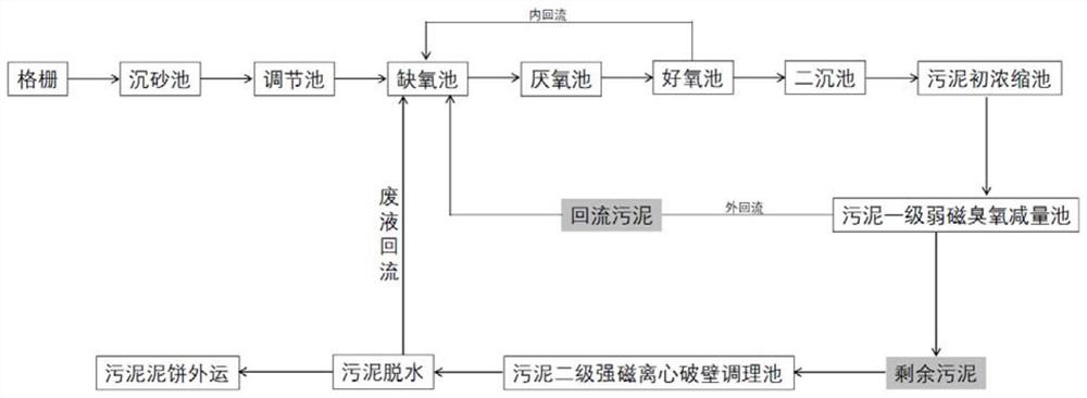
[0023] A transformation method applied to the in-situ reduction of sludge in traditional sewage treatment plants, figure 1 Be the technological process schematic diagram of the present invention, in traditional municipal sewage treatment process (as A 2 / O, but not limited to A 2 / O process), after the sludge in the initial concentration tank passes through the first-level weak magnetic ozone reduction tank, a part of the sludge enters the anoxic tank as return sludge, and the sludge ozone in the first-level weak magnetic ozone reduction tank is micro-nano When the ozone entrainment rate of the bubbles reaches 50%, and the ozone concentration in the water reaches 12mg / L, it enters A 2 / O system, the ozone micro-nano bubble adopts the conventional ozone generator and the micro-nano bubble generating device; the other part of the sludge enters the second-level strong magnetic centrifugal wall-breaking conditioning tank as the remaining sludge, and the ozone is reduced in the fi...

Embodiment 2

[0028] A transformation method applied to the in-situ reduction of sludge in traditional sewage treatment plants, figure 1 Be the technological process schematic diagram of the present invention, in traditional municipal sewage treatment process (as A 2 / O, but not limited to A 2 / O process), after the sludge in the initial concentration tank passes through the first-level weak magnetic ozone reduction tank, a part of the sludge enters the anoxic tank as return sludge, and the sludge ozone in the first-level weak magnetic ozone reduction tank is micro-nano When the ozone entrainment rate of the bubbles reaches 50%, and the ozone concentration in the water reaches 15mg / L, it enters A 2 / O system, the ozone micro-nano bubble adopts the conventional ozone generator and the micro-nano bubble generating device; the other part of the sludge enters the second-level strong magnetic centrifugal wall-breaking conditioning tank as the remaining sludge, and the ozone is reduced in the fi...


PUM

PropertyMeasurementUnit
Magnetic field strengthaaaaaaaaaa

Abstract

The invention relates to a transformation method for sludge in-situ reduction of a sewage treatment plant, which comprises the following steps: after sludge in a sludge primary concentration tank is treated by a sludge primary weak magnetic ozone reduction tank, one part of the sludge enters an anoxic tank as return sludge, and the other part of the sludge enters a sludge secondary strong magnetic centrifugal wall-breaking conditioning tank as residual sludge for treatment; the sludge secondary strong magnetic centrifugal wall-breaking conditioning tank adopts a strong magnetic field and an industrial centrifugal wall-breaking technology to reinforce sludge dewatering, sludge cakes are transported out after the wall-broken excess sludge is dewatered, and dewatering liquid flows back to an anoxic tank. Compared with the prior art, the method provided by the invention can achieve the effects of short time, high efficiency, reduction and energy saving, has no secondary pollution problem caused by drug addition, realizes sterilization and disinfection in the whole process through ozone circulation, and provides powerful technical support for in-situ reduction of sludge in a municipal sewage treatment plant.

Description

technical field [0001] The invention belongs to the technical field of solid waste treatment and recycling, and in particular relates to a transformation method for in-situ sludge reduction in sewage treatment plants. Background technique [0002] Traditional activated sludge process or A 2 The / O process is commonly used in the process of urban sewage treatment. It has a good treatment effect on organic matter and nutrients such as nitrogen and phosphorus, but it also has the problem of high excess sludge production. The cost of sludge treatment and disposal accounts for about 20% to 50% of the total cost of sewage treatment plants, and the treatment and disposal of excess sludge has become a difficult problem for sewage treatment plants. Sludge reduction technology is to minimize the amount of biological solids discharged from the entire sewage treatment system under the condition that the system effluent meets the discharge standards. It is an important way to solve the ...

Claims


Application Information

Patent Timeline
IPC IPC(8): C02F11/12C02F11/15C02F11/143
CPCC02F11/12C02F11/15C02F11/143Y02W10/20
Inventor 董滨陈思思沈丹妮
Owner TONGJI UNIV
Why Eureka
Try Eureka