Gas inlet and exhaust treatment system capable of achieving low emission of internal combustion engine

A technology for exhaust gas treatment and internal combustion engines, which is applied in the direction of exhaust gas treatment, combustion air/combustion-air treatment, fuel air intake, etc., which can solve the problems of high cumulative use cost, unfavorable long-term and large-scale promotion of after-treatment devices Use and other issues to achieve the effect of reducing dependence, saving operation and maintenance costs, and reducing emissions

Pending Publication Date: 2021-06-01
广西玉柴船电动力有限公司
View PDF10 Cites 0 Cited by
  • Summary
  • Abstract
  • Description
  • Claims
  • Application Information

AI Technical Summary

Problems solved by technology

Because DOC (Diesel Catalytic Oxidizer) uses rare and precious metals as catalysts, DPF (Soot Particulate Filter) uses ceramic filter carriers with complicated process and limited service life, and SCR needs to consume a large amount of NH 3 Urea solution, the cumulative use cost is relatively high. According to statistics, the purchase and maintenance cost of the exhaust after-treatment device of the internal combustion engine has accounted for more than 30% of the purchase and maintenance cost of the complete engine, or even higher, and because of failure or the end of service life will generate a large amount of Discarded post-processing devices need to be recycled and processed. In the long run, it is not conducive to the long-term and large-scale promotion and use of post-processing devices.
[0004] The main reason for the above problems is that the use of petrochemical oil, especially the intake air required for combustion is taken from the air, and the air contains a high proportion of nitrogen N 2 , As a result, the exhaust gas emitted by the internal combustion engine contains a large amount of harmful gases such as nitrogen oxides NOx and pollutants such as soot particles

Method used


Image

  • Gas inlet and exhaust treatment system capable of achieving low emission of internal combustion engine
  • Gas inlet and exhaust treatment system capable of achieving low emission of internal combustion engine

Examples


Embodiment Construction

[0018] The present invention will be further described below in conjunction with the specific embodiments in the accompanying drawings.

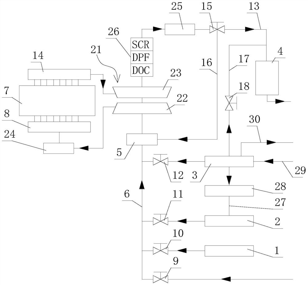
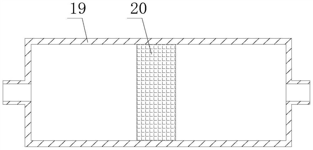
[0019] refer to figure 1 , 2 , an air intake and exhaust gas treatment system capable of achieving low emissions from an internal combustion engine, comprising an inert gas storage tank 1 , an oxygen storage tank 2 , an oxygen generator 3 , a black carbon combustion device 4 , and a mixer 5 . The output end of the inert gas storage tank 1, the output end of the oxygen storage tank 2, and the oxygen output end of the oxygen generator 3 are connected to the same gas supply pipe 6, and the gas supply pipe 6 is connected to the intake pipe 8 of the internal combustion engine 7, and the gas supply pipe 6 is provided with a mixing 5, the end of the gas supply pipe 6 away from the intake pipe 8 is provided with a first control valve 9, the output end of the inert gas storage tank 1 is provided with a second control valve 10, and the output end of ...


PUM


Abstract

The invention discloses a gas inlet and exhaust treatment system capable of achieving low emission of an internal combustion engine, and relates to the technical field of internal combustion engines. The technical problem that tail gas of the internal combustion engine contains a large amount of harmful gas and carbon cigarette pellet pollutants, the system comprises an inert gas storage tank, an oxygen storage tank, an oxygen generator, a black carbon combustion device and a mixer, the output end of the inert gas storage tank, the output end of the oxygen storage tank and the oxygen output end of the oxygen generator are connected to the same gas supply pipe, the gas supply pipe is connected to a gas inlet pipe of the internal combustion engine, the mixer is arranged on the gas supply pipe, the black carbon combustion device is connected to an exhaust pipe of internal combustion engine through a first tail gas pipe, a fifth control valve is arranged on the first tail gas pipe between the black carbon combustion device and the exhaust pipe, the fifth control valve is connected to the input end of the mixer through a second tail gas pipe, the oxygen output end of the oxygen generator is connected to the input end of the black carbon combustion device through a first blowdown pipe, and a sixth control valve is arranged on the first blowdown pipe.

Description

technical field [0001] The invention relates to the technical field of internal combustion engines, more specifically, it relates to an air intake and exhaust treatment system capable of realizing low emission of internal combustion engines. Background technique [0002] As we all know, internal combustion engines that use diesel, gasoline and other petrochemical oils as fuel need to inhale air in the cylinder, and produce carbon dioxide, nitrogen oxides NOx, hydrocarbons HC, soot particles, carbon dioxide CO 2 , and substances such as water. At the same time, in the composition of air, oxygen O 2 Accounting for 21%, nitrogen N 2 Oxygen O 2 with nitrogen N 2 ratio is almost constant. It can be seen that the oxygen O that is helpful for combustion 2 The content ratio is always at a low level, and during the combustion process, because a large amount of N 2 The existence of diesel will cause the internal combustion engine that uses diesel as fuel to emit a large amount ...

Claims


Application Information

Patent Timeline
Patent Type & Authority Applications(China)
IPC IPC(8): F02M35/10F02M25/00F02M25/12F02M26/19F01N13/00F01N3/02F02B37/00
CPCF02M35/10006F02M35/10255F02M25/00F02M25/12F02M26/19F01N13/009F01N3/02F02B37/00F01N2570/14F01N2250/02F01N2250/04F01N2250/06F01N2570/10F01N2570/12Y02T10/12
Inventor 李伟黄永仲
Owner 广西玉柴船电动力有限公司
Why Eureka
Try Eureka