Waste heat recovery system, boiler system and waste heat recovery method

A technology of waste heat recovery system and hot end, which is applied in heating system, heating mode, preheating, etc. It can solve the problems of limiting the promotion of waste heat recovery system, low efficiency of waste heat recovery and recovery, and corrosion of the outer surface of heat exchanger, so as to improve energy efficiency. Utilization rate, low overall cost, and the effect of improving utilization rate

Pending Publication Date: 2021-06-01
SHANGHAI DONGRUN HEAT EXCHANGE EQUIP MFG
View PDF0 Cites 1 Cited by
  • Summary
  • Abstract
  • Description
  • Claims
  • Application Information

AI Technical Summary

Problems solved by technology

[0005] However, the recovery efficiency of exhaust heat recovery in the prior art is low. If you want to improve the heat exchange efficiency, you need to reduce the temperature of the heat exchange medium, which will cause a large amount of water vapor in the exhaust gas to condense on the surface of the heat exchanger, thereby forming corrosion. The acidic solution will cause serious corrosion and rust on the outer surface o

Method used


Image

  • Waste heat recovery system, boiler system and waste heat recovery method
  • Waste heat recovery system, boiler system and waste heat recovery method
  • Waste heat recovery system, boiler system and waste heat recovery method

Examples


Embodiment 1

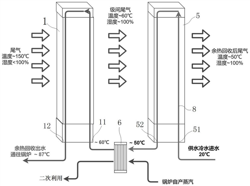
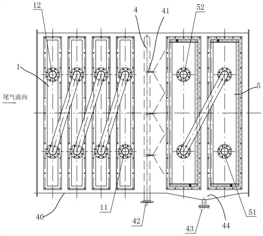
[0060] The waste heat recovery system is used to recover waste heat from the exhaust gas of gas-fired boilers or coal-fired boilers. It has a shell 40, which is pipe-shaped and connected in series in the exhaust gas pipeline, that is, the two ends are respectively sealed and docked with the exhaust gas pipe, so that the boiler The exhaust gas can pass through the waste heat recovery system, and the exhaust gas is discharged after heat exchange. The heat in the exhaust gas is transferred to the heat transfer medium of the waste heat recovery system, and the heat of the heat transfer medium is used for heating or introduced into the water inlet pipeline of the boiler system, etc., to realize Secondary use of heat. More specifically:

[0061] like Figure 1-3 As shown, the waste heat recovery system includes a casing 40 and a first heat exchanger 1 , a second heat exchanger 5 and a third heat exchanger 6 installed in the casing 40 . in:

[0062] The first heat exchanger 1 is a...

Embodiment 2

[0084] Embodiment 2 of the waste heat recovery system of the present invention: as Figure 4 As shown, the difference from Example 1 is that a fourth heat exchanger 7 is also provided after the second heat exchanger 5 to solve the whitening problem, specifically: the fourth heat exchanger 7 is an empty water exchange Heater, since there is basically no condensation here, it is also possible to use ordinary carbon steel + galvanized heat exchangers to reduce costs. The water inlet of the fourth heat exchanger is the same as the first water outlet of the first heat exchanger The water outlet of the fourth heat exchanger is connected with the water supply pipeline of the boiler system, that is, the first heat exchange medium 8 flows out of the first heat exchanger and then flows through the fourth heat exchanger. In other embodiments, The first heat exchange medium flowing out of the first heat exchanger can be divided into two paths, one path is introduced into the fourth heat e...

specific Embodiment

[0106] The specific embodiment of waste heat recovery method of the present invention: comprise the following steps:

[0107] S10, arrange the first heat exchanger and the second heat exchanger for air-water heat exchange in sequence along the flue gas flow direction in the flue, and the first heat exchanger and the second heat exchanger respectively have a first internal pipeline and a second internal pipeline Pipeline, the first heat exchanger is made of ordinary carbon steel, and the second heat exchanger is made of corrosion-resistant metal or non-metallic material;

[0108] S20. Installing a third heat exchanger outside the range of the flue gas hood, the third heat exchanger is a water-to-water heat exchanger having a hot end pipeline and a cold end pipeline;

[0109] S30, connecting the inlet of the cold end pipeline with the cooling water outlet of the second heat exchanger, and connecting the outlet of the cold end pipeline with the first water inlet of the first heat...


PUM


Abstract

The invention relates to a waste heat recovery system, a boiler system and a waste heat recovery method. The waste heat recovery system comprises a first heat exchanger and a second heat exchanger which are sequentially arranged in a flue, wherein the first heat exchanger is an air-water heat exchanger made of a common material; the second heat exchanger is an air-water heat exchanger made of a corrosion-resistant material; a plate-type third heat exchanger is arranged between the two heat exchangers; a first heat exchange medium sequentially flows through the second heat exchanger, the third heat exchanger and the first heat exchanger, exchanges heat with the flue gas in the second heat exchanger and the first heat exchanger and exchanges heat with steam introduced into the boiler system in the third heat exchanger; a temperature control module is arranged to control the temperature of a first heat exchange medium in the first heat exchanger to be within a set temperature range slightly higher than the dew point temperature, so that water vapor in the flue gas cannot be condensed on the surface of the first heat exchanger and can be concentrated on the surface of the second heat exchanger; and good corrosion resistance is achieved on the premise of efficient heat exchange, and the overall cost is low.

Description

technical field [0001] The invention relates to a waste heat recovery system, a boiler system and a waste heat recovery method. Background technique [0002] With the continuous deepening of my country's energy-saving and emission-reduction policies, the original coal-fired boilers that provide steam for enterprises or residents are gradually replaced by gas-fired boilers fueled by natural gas. Taking an industrial park as an example, 3 gas-fired boilers can generate 150 steam per hour. tons, its consumption capacity is huge, and the temperature of the exhaust gas after combustion is around 110-150°C. The main component of natural gas is methane CH4. According to its combustion chemical formula: CH4+2O2=CO2+2H2O, 1m 3 After the natural gas is fully burned, the calorific value is about 35.88MJ without considering the condensation. When considering the condensation heat release, because the water vapor will release a lot of heat when it condenses, the calorific value can be as...

Claims


Application Information

Patent Timeline
IPC IPC(8): F22D1/00F23J15/06F24D15/00
CPCF22D1/003F23J15/06F24D15/00F24D2200/18Y02E20/30
Inventor 陈杰郭云龙高大伟刘冰
Owner SHANGHAI DONGRUN HEAT EXCHANGE EQUIP MFG
Why Eureka
Try Eureka