
Coal gasification slag recycling system and method

A coal gasification slag and flue gas technology, applied in gasification process, manufacture of combustible gas, solid fuel, etc., can solve the problems of high cost and difficulty in waste slag treatment, and achieve low cost, reduce ecological environment pressure, and save resources Effect

Active Publication Date: 2021-06-04
KEDA MAS CLEAN ENERGY
View PDF3 Cites 4 Cited by
  • Summary
  • Abstract
  • Description
  • Claims
  • Application Information

AI Technical Summary

Problems solved by technology

[0006] Aiming at the difficulty and high cost of existing waste slag treatment, the present invention provides a system and method for recycling coal gasification slag

Method used


Image

  • Coal gasification slag recycling system and method
  • Coal gasification slag recycling system and method

Examples


Embodiment 1

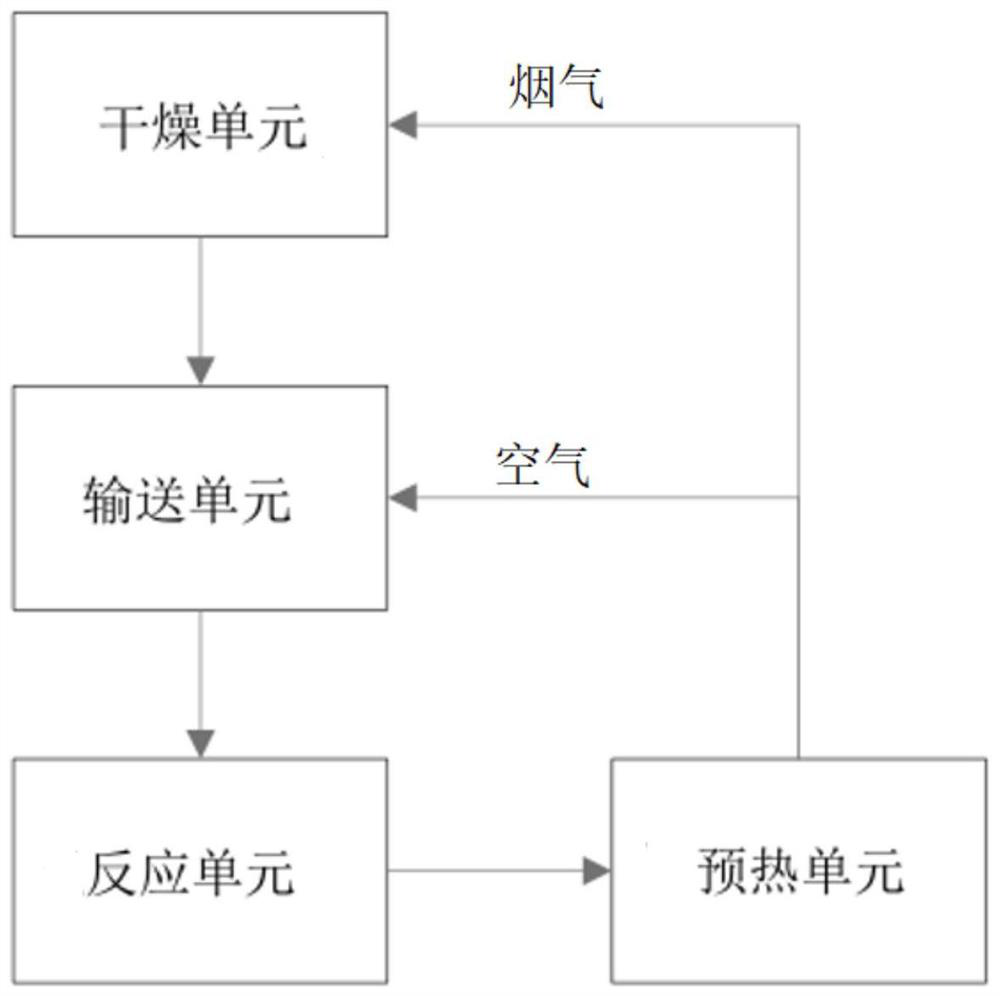
[0035] Such as figure 1As shown, a coal gasification slag recycling system includes a drying unit 1, a conveying unit 2, a reaction unit 3 and a preheating unit 4 connected in sequence; the drying unit 1 is used for drying and preheating the coal gasification slag; Unit 2 is used to transport and reheat the dried and preheated coal gasification slag; the reaction unit 3 is used to burn the reheated coal gasification slag; the preheating unit 4 is used to reheat the reaction unit 3 The flue gas produced is recycled. Specifically, the preheating unit 4 includes an air inlet, an air outlet and a flue gas outlet, the air outlet is connected to the conveying unit 2, the flue gas outlet is connected to the drying unit 1, and the heat exchange between the high temperature flue gas and the normal temperature air is carried out in the preheating unit 4 , the high-temperature flue gas is the flue gas generated in the reaction unit 3, and the normal-temperature air is the air coming in ...

Embodiment 2

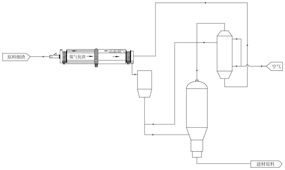
[0045] Such as figure 2 As shown, it is basically the same as in Example 1. Specifically, in this implementation, the drying unit 1 is a drying kiln, which includes a drying cylinder, one end of the drying cylinder is the inlet of coal gasification slag, the other end is the outlet of coal gasification slag and the The end is connected to the conveying unit 2, and the inside of the drying cylinder is provided with a heat exchange tube, which is connected to the flue gas outlet in the preheating unit 4, and the flow direction of the flue gas in the drying cylinder is opposite to the flow direction of the coal gasification slag . Specifically, with figure 2 As a benchmark, the left end of the drying cylinder is the inlet of coal gasification slag, the right end of the drying cylinder is the outlet of coal gasification slag, the flow direction of coal gasification slag is from left to right, and the flow direction of low-temperature flue gas in the drying cylinder is from Rig...


PUM


Abstract

The invention discloses a coal gasification slag recycling system and method, and belongs to the field of coal chemical industry waste slag treatment. Directed at the problems of high waste slag treatment difficulty and high cost in the prior art, the invention provides a coal gasification slag recycling system, which comprises a drying unit, a conveying unit, a reaction unit and a preheating unit which are connected in sequence; the preheating unit comprises an air inlet, an air outlet and a smoke outlet, the air outlet is connected with the conveying unit, and the smoke outlet is connected with the drying unit. High-temperature flue gas generated by combustion of the gasification slag is recycled, the high-temperature flue gas exchanges heat with normal-temperature air, then the cooled flue gas and the heated air are conveyed to different units correspondingly to conduct heat treatment of different degrees on the gasification slag, and the gasification slag does not need to be mixed with other raw material media in the combustion process, the self-stable reaction of the solid waste can be realized, and the energy consumption is greatly reduced. The coal gasification slag recycling method disclosed by the invention is simple and convenient to operate, stable in operation, low in cost, resource-saving and good in economic effect.

Description

technical field [0001] The invention belongs to the field of coal chemical waste slag treatment, and more specifically relates to a system and method for recycling coal gasification slag. Background technique [0002] Gasification technology is the leading and core technology in the field of coal chemical industry. It is one of the main ways to convert solid coal into gaseous synthesis gas. The application of gasification technology produces a large amount of gasification slag, which is a solid waste product. The gasification slag produced in my country every year is mainly stored in landfills and slag yards. After storage, it is in the form of black powder. Land occupation, dust pollution, and water system pollution are serious problems, which seriously affect the local ecological environment. At present, combined with the characteristics of gasification slag resources, the development and utilization of carbon materials, the preparation of ceramic materials, and the prepar...

Claims


Application Information

Patent Timeline
Patent Type & Authority Applications(China)
IPC IPC(8): C10J3/72C10J3/66C10L5/48
CPCC10J3/66C10J3/72C10J3/723C10J2300/093C10J2300/1625C10J2300/1628C10J2300/1631C10L5/48Y02P20/129
Inventor 李挺白勇毕一鸣朱晨军张冬临
Owner KEDA MAS CLEAN ENERGY
Learn More