
Mechanical sealing structure for air turbine assembly of hypersonic aircraft

An air turbine, hypersonic technology, applied in the direction of engine seal, mechanical equipment, machine/engine, etc., can solve the problem of high temperature environment of cavity

Active Publication Date: 2021-06-08
BEIHANG UNIV
View PDF9 Cites 2 Cited by
  • Summary
  • Abstract
  • Description
  • Claims
  • Application Information

AI Technical Summary

Problems solved by technology

At the interface of the turbine-rotating-static system, the high-temperature gas working medium in the meridian flow channel invades the turbine rotating-static disc cavity, resulting in a high-temperature environment inside the cavity, and the conventional rubber ring-assisted mechanical seal structure is no longer applicable here

Method used


Image

  • Mechanical sealing structure for air turbine assembly of hypersonic aircraft

Examples


Embodiment Construction

[0023] The following will clearly and completely describe the technical solutions in the embodiments of the present invention with reference to the accompanying drawings in the embodiments of the present invention. Obviously, the described embodiments are only some, not all, embodiments of the present invention. Based on the embodiments of the present invention, all other embodiments obtained by persons of ordinary skill in the art without making creative efforts belong to the protection scope of the present invention.

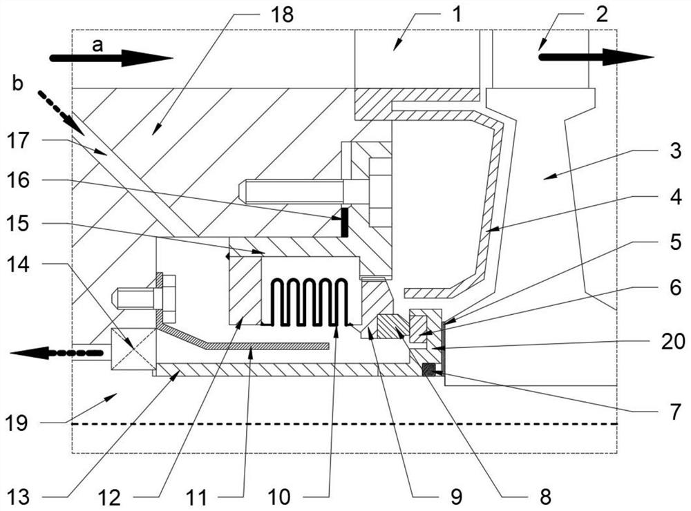
[0024] The purpose of the present invention is to provide a mechanical seal structure for a hypersonic aircraft air turbine assembly, so as to solve the problems existing in the prior art.

[0025] In order to make the above objects, features and advantages of the present invention more comprehensible, the present invention will be further described in detail below in conjunction with the accompanying drawings and specific embodiments.

[0026] The mechanical ...


PUM


Abstract

The invention discloses a mechanical sealing structure for an air turbine assembly of a hypersonic aircraft. The mechanical sealing structure comprises a metal corrugated pipe, a corrugated pipe support, a clamping base, a static ring, a movable ring, a flexible graphite packing, a flexible graphite gasket, a baffle plate and a metal base. Fuel oil for cooling is injected into a bearing cavity through an oil conveying hole and flows around the baffle plate, and flowing and heat exchange of the area nearby the corrugated pipe are enhanced. The oil flows into a bearing ring cavity along an interlayer between a shaft and the baffle plate and finally flows out of a bearing cavity. The corrugated pipe is fixed by welding a metal support and the corrugated pipe, so that a good sealing effect can be achieved, and the strength of the joint can be ensured to reach the standard. Circumferential rotation is limited in a mode that grooves and convex teeth are arranged on the outer circle and matched with each other, and axial displacement compensation can be provided. The mode that the metal base clamps a silicon carbide moving ring is adopted, and the eccentric motion degree of the moving ring is reduced. The sealing device has the characteristics of high working temperature and rotating speed upper limit, good cooling and heat exchange effects, lower bearing working temperature and simple and reliable structure.

Description

technical field [0001] The invention relates to the technical field of mechanical seals, in particular to a mechanical seal structure for hypersonic aircraft air turbine components. Background technique [0002] At present, with the development of aerospace technology, the human demand for the ultimate speed of aircraft is increasing, and hypersonic aircraft has become a research hotspot and foreword in the field of aerospace. In the development process of hypersonic vehicles, propulsion power technology is the most critical technical support. When the design speed of the aircraft is greater than Mach 3, the traditional turbojet or turbofan engine can no longer be used as a power source, and the turbo-ram combined cycle has become the mainstream solution for hypersonic power. However, since the ramjet engine has no rotating parts, the traditional solution of driving the generator to generate electricity through the rotating shaft of the engine cannot be adopted. Therefore, ...

Claims


Application Information

Patent Timeline
Patent Type & Authority Applications(China)
IPC IPC(8): F01D11/00F16J15/16F16J15/18F16C37/00
CPCF01D11/003F16J15/162F16J15/182F16C37/00
Inventor 徐国强董苯思赵广龙闻洁孙京川
Owner BEIHANG UNIV
Learn More