Unlock instant, AI-driven research and patent intelligence for your innovation.

Micro-lens array two-axis linkage machining method

A technology of microlens array and processing method, applied in metal processing, metal processing equipment, metal processing mechanical parts, etc., can solve the problems of inability to process large aspect ratio microlens arrays, low processing efficiency, and inability to realize convex lens array processing.

Active Publication Date: 2021-06-11
SHANDONG UNIV
View PDF9 Cites 2 Cited by
  • Summary
  • Abstract
  • Description
  • Claims
  • Application Information

AI Technical Summary

Problems solved by technology

However, due to the impact of the tool back angle, slow tool servo turning can not process microlens arrays with large depth-to-diameter ratio. Due to the limitation of Z-axis acceleration, the processing efficiency is very low. Unable to realize the processing of convex lens array
Although the ultra-precision milling process is not affected by the back angle of the tool, it can realize the processing of the microlens array with a large depth-to-diameter ratio, but it needs to add a high-precision milling axis

Method used


Image

  • Micro-lens array two-axis linkage machining method
  • Micro-lens array two-axis linkage machining method
  • Micro-lens array two-axis linkage machining method

Examples


Embodiment 1

[0034] This example is processed as figure 1 As shown in the 5X5 quadrilateral aspheric microlens array, the cross-sectional curve of the array structure unit is the processing trajectory curve, and the processing trajectory curve can be described by the following formula:

[0035]

[0036] In the formula: R is the vertex circle radius of the high degree curve, and K is the conic coefficient. figure 1 Among them, r is the opening radius of the unit microlens, and H is the height of the spherical cap.

[0037] The specific processing method is as follows. The equipment used is a five-axis ultra-precision machine tool. The two-axis linkage ultra-precision machining of the microlens array is realized by installing a precision displacement platform on the spindle of the machine tool, including the following steps:

[0038] Step 1: If image 3 As shown, a precision rotary base 2, a precision displacement platform 3, a precision displacement platform 4 and a rotary workpiece 5 ...

Embodiment 2

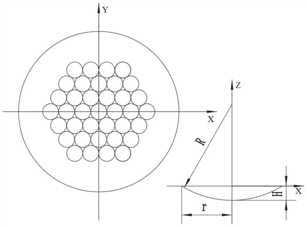
[0045] The processing device and processing method of this embodiment are completely the same as those of Embodiment 1, and will not be repeated here. The difference between it and Embodiment 1 lies in that the arrays processed are different. In this embodiment, as figure 2 Taking the spherical microlens array as an example, through two-axis linkage processing such as figure 2 Shown is a hexagonal array of spherical microlenses. figure 2 Among them, r is the opening radius of the unit microlens, H is the spherical crown height, and R is the spherical radius. The cross-sectional curve of the array structure unit, that is, the machining trajectory curve is an arc curve. The diamond arc turning tool moves from the edge of the spherical microlens to the center of rotation along the machining trajectory curve, and keeps the turning tool arc surface tangent to the machining trajectory curve at all times. The X and Z two-axis linkage of the machine tool realizes the high-precisi...


PUM


Abstract

The invention discloses a micro-lens array two-axis linkage machining method which comprises the steps that a precise rotation base, an X-direction precision displacement platform, a Y-direction precision displacement platform and a rotation workpiece are installed on a machine tool spindle, the X-direction precision displacement platform and the Y-direction precision displacement platform are used for precise feeding in the two axial directions respectively, the position of the rotation workpiece relative to the machine tool spindle is adjusted, and the axis of the rotation workpiece and the axis of the machine tool spindle are concentric. Firstly, a workpiece center micro lens is machined, a main shaft controls the workpiece to freely rotate at a certain rotating speed, a diamond arc turning tool moves from the edge of the spherical or aspheric micro lens to a rotation center along a machining track curve, and the turning tool arc surface is kept tangent to the machining track curve of the micro lens all the time. High-precision rapid forming of the central micro-lens array is realized through linkage of the X axis and the Z axis. The X-direction precision displacement platform and the Y-direction precision displacement platform are adjusted, the axis of the Nth micro lens array is adjusted to coincide with the machine tool spindle till machining of the whole in-plane micro lens array is completed, and the final micro lens array is obtained.

Description

technical field [0001] The invention relates to a microlens array processing method, in particular to a microlens array two-axis linkage processing method. Background technique [0002] Microlens array, as a typical optical microstructure, refers to a long microstructure array composed of microlens units with a diameter of 10 μm to 1 mm arranged in a specific shape. Compared with traditional flat mirrors and aspheric lenses, microlens arrays have the advantages of small unit size, high integration, and light weight. It can be applied to many new optical systems to realize new functions that cannot be realized by traditional lenses, so it plays an increasingly important role in the fields of civil and national defense. The processing methods of microlens array mainly include photoresist hot melting method, femtosecond laser acid etching method, reactive ion beam etching technology, imprinting method, etc. However, these technologies are still immature, and have disadvantage...

Claims


Application Information

Patent Timeline
IPC IPC(8): B23Q1/26B23Q5/22B23Q15/06
CPCB23Q1/26B23Q5/22B23Q15/06Y02P40/57
Inventor 姚鹏于世孟孙旭峰周嘉斌黄传真邹斌褚东凯
Owner SHANDONG UNIV
Features
  • R&D
  • Intellectual Property
  • Life Sciences
  • Materials
  • Tech Scout
  • Unparalleled Data Quality
  • Higher Quality Content
  • 60% Fewer Hallucinations
Learn More