
Laminar flow wing transition position measurement test method

A test method and wing technology, applied in the field of wind tunnel tests, can solve problems such as low spatial resolution, surface flow field interference, and insufficient thickness space, and achieve high spatial resolution and reduce model design.

Pending Publication Date: 2021-06-11
INST OF HIGH SPEED AERODYNAMICS OF CHINA AERODYNAMICS RES & DEV CENT
View PDF5 Cites 10 Cited by
  • Summary
  • Abstract
  • Description
  • Claims
  • Application Information

AI Technical Summary

Problems solved by technology

There are many defects in this method: First, because the sensor protruding or recessing on the surface of the wing model will interfere with the surface flow field, which will cause differences in the airflow velocity or flow field structure on the surface of the wing, which will cause surface temperature measurement errors, so the sensor is required Strictly flush with the surface of the wing model, it is difficult to install the sensor
2. To install the temperature sensor, it is necessary to make holes and grooves on the wing model at the installation position and the wiring channel, which increases the difficulty of model design and processing, and increases the cost of model design and processing
3. On thin parts such as the wingtip or the trailing edge of the wing, the temperature sensor may not be installed due to insufficient thickness space, so that the transition position measurement of the above-mentioned area cannot be performed
4. The temperature sensor belongs to the discrete point measurement method, which can only measure several points on the surface of the wing. The spatial resolution is very low, and the accurate transition position of the laminar flow wing cannot be obtained.
Optical methods can also be used to measure the transition position of the wing. This type of method has the advantage of surface measurement. Commonly used measurement methods include phase change heat maps, temperature-sensitive liquid crystals, infrared heat maps, and phosphorescence heat maps. However, due to their inherent Defects restrict the scope of application. For example, phase change heat map and temperature-sensitive liquid crystal can only be used as semi-quantitative measurement techniques. The spatial resolution of infrared cameras is not high and is greatly affected by the transmittance of transparent materials in the measurement light path. Phosphorescence heat map technology is affected by inorganic phosphorescent substances. Surface film formation method and process constraints are obvious, etc.
[0004] The traditional temperature sensor transition measurement method is difficult to install, has large flow disturbance, high cost of model design and processing, can only perform point measurement, and has low spatial resolution. The commonly used phase change heat map, temperature sensitive liquid crystal, infrared heat map and phosphorescence Optical measurement methods such as heat maps restrict the scope of application due to their own inherent defects, and cannot accurately measure the transition position of the laminar airfoil model
The temperature-sensitive coating method has the advantages of surface measurement, high spatial resolution, difficulty in model design and processing, low cost, no disturbance of incoming flow, and accurate judgment of transition position. However, it has not been applied to the measurement of laminar flow wing transition position. Relevant test methods urgently need to be established

Method used


Image

  • Laminar flow wing transition position measurement test method
  • Laminar flow wing transition position measurement test method
  • Laminar flow wing transition position measurement test method

Examples


Embodiment

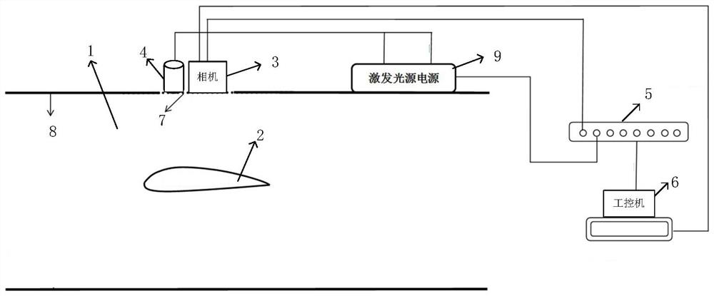
[0059] The test model of this embodiment is a laminar airfoil model with a sweep angle of 20° and a chord length of 200 mm. The camera is a scientific grade CCD camera with a gray scale dynamic range of 14 bits and a spatial resolution of 1600×1200 pixels. The lens used is an 8mm fixed-focus lens, and the filter used is a 650nm high-pass filter. The main peak wavelength of the excitation light source is 400nm, and the transmittance of the filter is greater than 90%. 12W. The synchronous trigger can set the period, delay, pulse width and number of pulses of the pulse signal to realize the timing control of camera exposure and excitation light source. It is a single input and 8 outputs, and the control accuracy is less than 10 nanoseconds. The temperature-sensitive coating used has an excitation peak spectrum wavelength of 400nm and an emission peak spectrum wavelength of 615nm. Within the temperature range of 273K to 333K, the temperature sensitivity is greater than 1% / K, the ...


PUM

PropertyMeasurementUnit
Sensitivityaaaaaaaaaa

Abstract

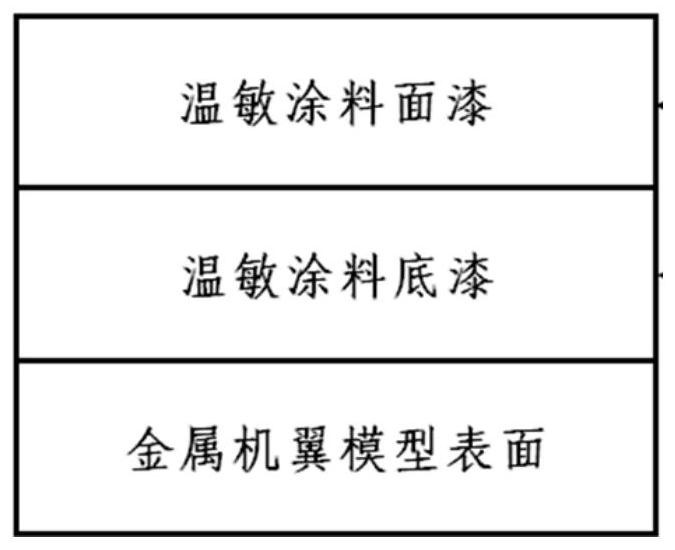
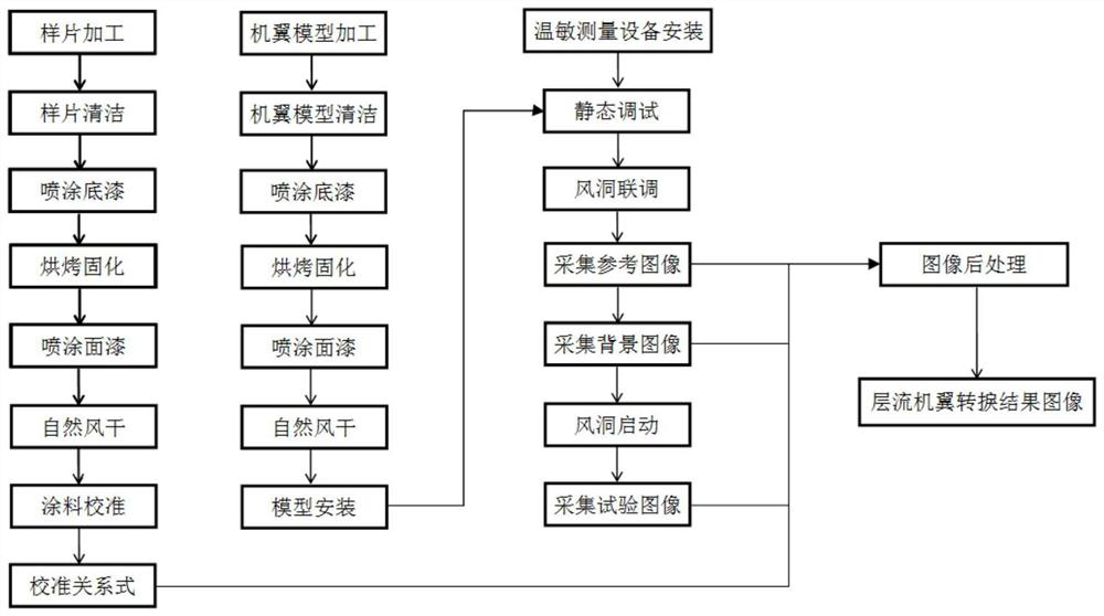
The invention discloses a laminar flow wing transition position measurement test method. The method comprises the following steps: 1, processing a laminar flow wing model and a sample wafer based on a temperature-sensitive paint technology; 2, obtaining a calibration relational expression of the temperature and the light intensity of the sample in a calibration cabin; 3, establishing a test scene; 4, determining static debugging parameters in the temperature-sensitive coating measuring system; 5, performing joint debugging on the temperature-sensitive coating measurement system and the wind tunnel measurement and control system to obtain a reference image, a background image and a sequence test image; and 6, carrying out test image acquisition on different states of the laminar flow wing, and carrying out post-processing on the test acquired images to obtain a gas flow transition image on the surface of the laminar flow wing model. According to the laminar flow wing transition position measurement test method provided by the invention, a laminar flow wing test mode based on the temperature-sensitive paint is creatively established, and compared with the prior art, the test effect has the remarkable advantages of high resolution and accurate transition position judgment.

Description

technical field [0001] The invention belongs to the technical field of wind tunnel tests, and in particular relates to a test method capable of accurately measuring the transition position on the surface of a laminar airfoil model without destroying the model surface in the wind tunnel test. Background technique [0002] In order to achieve the goal of saving energy, reducing emissions and increasing the flight range, aircraft aerodynamic drag reduction technology has become a key research object for aerodynamic designers. With the rapid development of aviation industry design technology and manufacturing technology, laminar flow design has gradually become possible. For civil airliners, the laminar flow wing design technology can reduce frictional resistance by about 30%, which in turn can increase cruise efficiency by about 15%. noise. In order to test the laminar flow wing design method and the aerodynamic characteristics of the laminar flow wing, it is necessary to meas...

Claims


Application Information

Patent Timeline
IPC IPC(8): G01M9/00G01M9/06G01M9/08B64F5/60
CPCG01M9/00G01M9/06G01M9/08B64F5/60
Inventor 刘祥熊健王红彪黄辉刘大伟李永红史晓军
Owner INST OF HIGH SPEED AERODYNAMICS OF CHINA AERODYNAMICS RES & DEV CENT
Learn More