Organic synthesis wastewater low-emission system

An organic synthesis, low-emission technology, used in natural water treatment, special compound water treatment, mechanical vibration water/sewage treatment, etc., can solve the problem of insufficient decomposition of aerobic organic matter, sewage does not achieve the expected effect, and affect the aeration efficiency. and other problems, to achieve the effect of improving the overall current efficiency, improving the oxidation efficiency, and strengthening mutual coupling.

Inactive Publication Date: 2021-06-18
重庆迪笙宏环保科技有限公司
View PDF11 Cites 0 Cited by
  • Summary
  • Abstract
  • Description
  • Claims
  • Application Information

AI Technical Summary

Problems solved by technology

[0002] With the rapid development of the country's economy, people's living standards are getting better and better, and the level of industrialization is getting higher and higher. Industrial sewage and domestic wastewater are increasing rapidly. In the process of sewage treatment, there will be an aerobic pool, which is to The sewage in the pool is oxygenated to provide the required oxygen for the microorganisms in the aerobic pool. This link is called aeration. Aeration is an important process link in the sewage treatment process. At present, there are two types of aeration, mechanical aeration and blast aeration, but most sewage treatment plants will choose an aeration method to aerate the aerobic tank, sometimes due to insufficient aeration, some aerobic organic matter is not fully decomposed, affecting aeration The efficiency, so that the sewage does not achieve the expected effect in the process of treatment

Method used


Image

  • Organic synthesis wastewater low-emission system
  • Organic synthesis wastewater low-emission system
  • Organic synthesis wastewater low-emission system

Examples


Embodiment 1

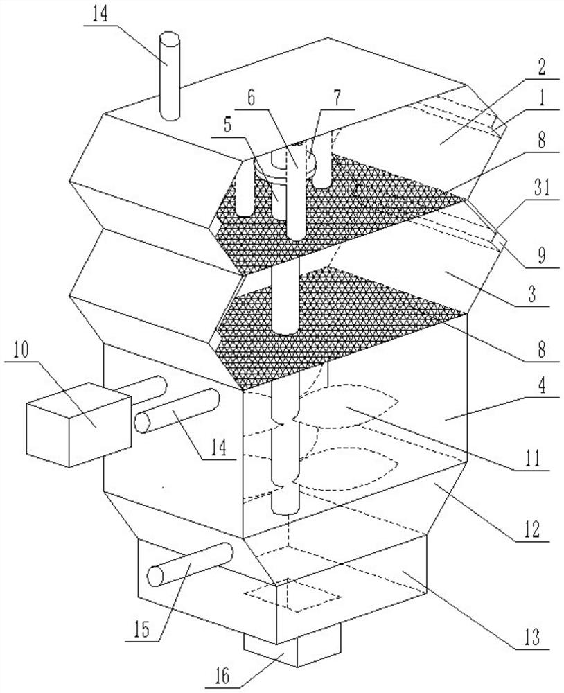
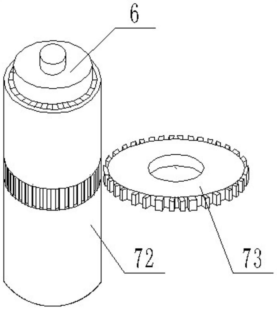
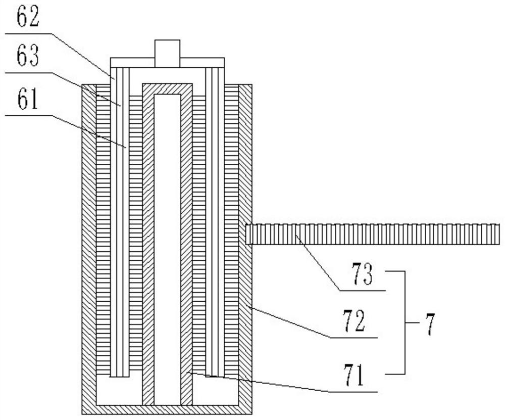
[0021] Such as Figure 1-3 As shown, a low-emission system for organic synthetic wastewater includes a shell, and the shell is divided into an upper radical oxidation zone 2, a photocatalytic reaction zone 3, a lower free radical oxidation zone 4, a settling zone 12 and A buffer zone 13, the upper free radical oxidation zone 2 is provided with a water inlet pipe 14, the settling zone 12 is provided with an outlet pipe 15, the buffer zone 13 is provided with a sludge pipe 16, and the housing is vertically provided with A central rotating shaft 5, the central rotating shaft 5 runs through the upper radical oxidation zone 2, the photocatalytic reaction zone 3 and the lower free radical oxidation zone 4, and the upper radical oxidation zone 2 is provided with a plurality of An electrolysis electrode 6, a cleaning device 7 is provided between the electrolysis electrode 6 and the central rotating shaft 5, a double-layer photocatalytic net 8 is provided in the photocatalytic reaction...

Embodiment 2

[0023] Such as Figure 1-3 As shown, a low-emission system for organic synthetic wastewater includes a shell, and the shell is divided into an upper radical oxidation zone 2, a photocatalytic reaction zone 3, a lower free radical oxidation zone 4, a settling zone 12 and A buffer zone 13, the upper free radical oxidation zone 2 is provided with a water inlet pipe 14, the settling zone 12 is provided with an outlet pipe 15, the buffer zone 13 is provided with a sludge pipe 16, and the housing is vertically provided with A central rotating shaft 5, the central rotating shaft 5 runs through the upper radical oxidation zone 2, the photocatalytic reaction zone 3 and the lower free radical oxidation zone 4, and the upper radical oxidation zone 2 is provided with a plurality of An electrolysis electrode 6, a cleaning device 7 is provided between the electrolysis electrode 6 and the central rotating shaft 5, a double-layer photocatalytic net 8 is provided in the photocatalytic reaction...

Embodiment 3

[0026] Such as Figure 1-3 As shown, a low-emission system for organic synthetic wastewater includes a shell, and the shell is divided into an upper radical oxidation zone 2, a photocatalytic reaction zone 3, a lower free radical oxidation zone 4, a settling zone 12 and A buffer zone 13, the upper free radical oxidation zone 2 is provided with a water inlet pipe 14, the settling zone 12 is provided with an outlet pipe 15, the buffer zone 13 is provided with a sludge pipe 16, and the housing is vertically provided with A central rotating shaft 5, the central rotating shaft 5 runs through the upper radical oxidation zone 2, the photocatalytic reaction zone 3 and the lower free radical oxidation zone 4, and the upper radical oxidation zone 2 is provided with a plurality of An electrolysis electrode 6, a cleaning device 7 is provided between the electrolysis electrode 6 and the central rotating shaft 5, a double-layer photocatalytic net 8 is provided in the photocatalytic reaction...


PUM


Abstract

The invention relates to the technical field of wastewater, in particular to an organic synthesis wastewater low-emission system which comprises a shell, the shell is divided into an upper free radical oxidation zone, a photocatalytic reaction zone and a lower free radical oxidation zone from top to bottom, and a central rotating shaft is vertically arranged in the shell; the central rotating shaft penetrates through the upper free radical oxidation zone, the photocatalytic reaction zone and the lower free radical oxidation zone, a plurality of electrolysis electrodes are arranged in the upper free radical oxidation zone around the central rotating shaft, a cleaning device is arranged between the electrolysis electrodes and the central rotating shaft, double layers of photocatalytic nets are arranged in the photocatalytic reaction zone, and an ultraviolet light source is arranged between the two layers of photocatalytic nets. The lower free-radical oxidation zone is connected with a medicament box through a pipeline, and stirring blades are arranged at one end, positioned in the lower free-radical oxidation zone, of the central rotating shaft. Compared with the prior art, by arranging a plurality of wastewater treatment areas, the rate of generating active free radicals is increased, the organic matter decomposition capacity effect is more than two times that of ozone, the cost is low, and the energy consumption is low.

Description

technical field [0001] The invention relates to the technical field of wastewater, in particular to a low-discharge system for organic synthetic wastewater. Background technique [0002] With the rapid development of the country's economy, people's living standards are getting better and better, and the level of industrialization is getting higher and higher. Industrial sewage and domestic wastewater are increasing rapidly. In the process of sewage treatment, there will be an aerobic pool, which is to The sewage in the pool is oxygenated to provide the required oxygen for the microorganisms in the aerobic pool. This link is called aeration. Aeration is an important process link in the sewage treatment process. At present, there are two types of aeration, mechanical aeration and blast aeration, but most sewage treatment plants will choose an aeration method to aerate the aerobic tank, sometimes due to insufficient aeration, some aerobic organic matter is not fully decomposed,...

Claims


Application Information

Patent Timeline
Patent Type & Authority Applications(China)
IPC IPC(8): C02F9/06C02F101/30C02F103/36
CPCC02F9/00C02F1/30C02F1/4672C02F1/46109C02F2001/46142C02F1/36C02F1/725C02F1/722C02F2305/023C02F2209/08C02F2209/06C02F2305/10C02F2103/36C02F2101/30
Inventor 王春晓邓攀唐崇峻梁彪
Owner 重庆迪笙宏环保科技有限公司
Why Eureka
Try Eureka