A method and apparatus for generating a high-power vortex laser

A high-power, vortex technology, used in optics, optical components, instruments, etc., can solve the problems of high-power laser, broadband laser dispersion, low diffraction efficiency, etc., to improve energy utilization, solve dispersion problems, suppress side lobe effect

Active Publication Date: 2022-08-02
INST OF OPTICS & ELECTRONICS - CHINESE ACAD OF SCI
View PDF15 Cites 0 Cited by
  • Summary
  • Abstract
  • Description
  • Claims
  • Application Information

AI Technical Summary

Problems solved by technology

Although methods such as spatial light modulator, grating method and holography method can flexibly generate vortex beams with different modes, the diffraction efficiency is very low
Most of the above methods use phase optical components, which cannot withstand high-power lasers, and also have the effect of dispersion on broadband lasers
The spiral mirrors currently used, although capable of generating high-power vortex lasers, can only generate one mode

Method used


Image

  • A method and apparatus for generating a high-power vortex laser
  • A method and apparatus for generating a high-power vortex laser
  • A method and apparatus for generating a high-power vortex laser

Examples


Embodiment 1

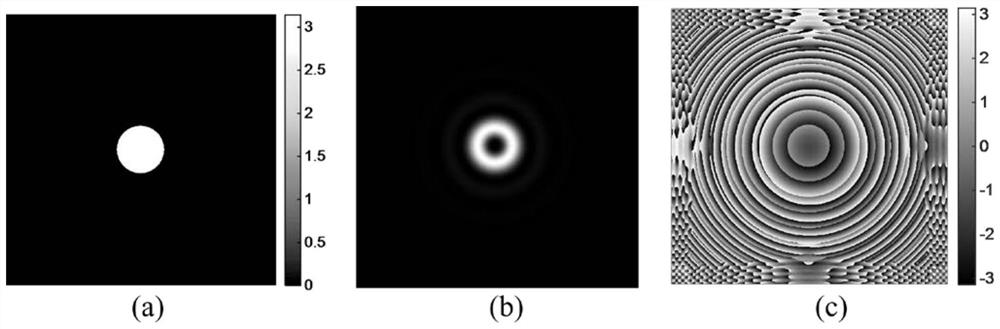
[0046] Example 1: This example shows the results of generating a vortex laser by using a continuous surface deformable mirror to load an annular helical shape with a topological charge equal to 2 for the annular light field emitted by an unstable cavity laser.

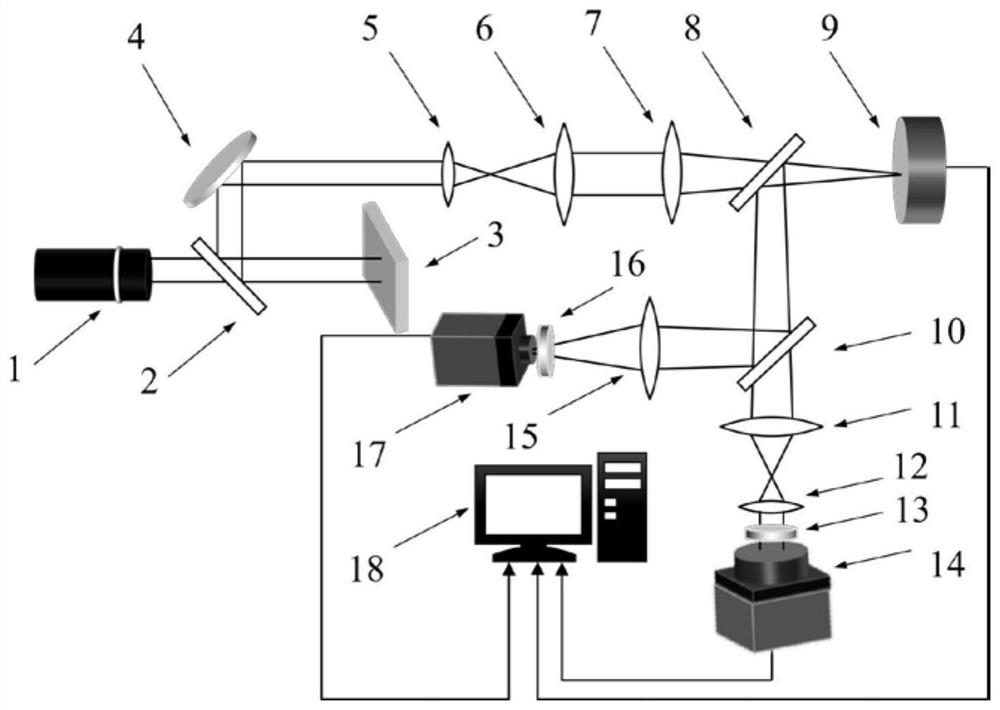
[0047] For the annular light field emitted by the unstable cavity laser, figure 1 The device in removes the first focusing lens 7, and the optical shaping plate 3 is not loaded with a surface shape and is a mirror. First, the voltage of the continuous surface deformable mirror 9 is set to zero, and the annular light field emitted by the laser 1 passes through the first lens 5 and the second lens 6, and then expands to the beam width required by the continuous surface deformable mirror 9, and then passes through the second beam splitting prism 8 It reaches the continuous surface deforming mirror 9, is reflected by the continuous surface deforming mirror 9 and the second beam splitting prism 8, reaches the third beam spl...

Embodiment 2

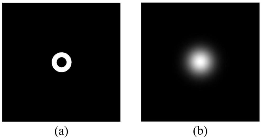
[0061] Embodiment 2: This embodiment shows that after the Gaussian light field emitted by the laser 1 is pre-shaped, the continuous surface deformable mirror 9 is used to fit the annular helical shape with a topological charge of 1 to generate a high-power vortex laser.

[0062] For a solid light field, figure 1 The device shown remains unchanged. First, the Gaussian light field emitted by the laser 1 passes through the first beam splitter 2, and then is irradiated on the optical shaping plate 3. The optical shaping plate 3 and the reflector 4 send the light field into the first lens 5 and the second lens 6 to form an expansion lens. The beam system, after the beam is expanded, is focused on the continuous surface deformation mirror 9 through the first focusing lens 7, and an annular light field is obtained on the plane where the continuous surface deformation mirror 9 is located. It is reflected by the continuous surface deforming mirror 9 to the second beam splitter 8, and ...


PUM


Abstract

The present invention relates to a method and apparatus for generating a high power vortex laser. The invention mainly uses a continuous surface deformable mirror to fit the annular helical shape, and can directly generate a high-power vortex laser for the annular light field emitted by the unstable cavity laser. For the solid light field emitted by other lasers, it needs to be preset. It is shaped into a ring light field, and then loaded on a continuous surface deformable mirror to generate a high-power vortex laser. There is an adaptive optics system in the device, which can correct the aberrations of the system and the input light field before generating the high-power vortex laser, and obtain a high-quality incident light field. This method uses a ring-shaped optical field to generate a vortex laser, which has the advantage of suppressing side lobes. The continuous surface deformable mirror can also withstand high-power lasers. The reflective structure can also solve the problem of broadband laser dispersion. The surface shape is flexible and can generate different mode of the vortex laser. The method is simple to operate and has great application prospects in the fields of optical processing and particle trapping.

Description

technical field [0001] The invention belongs to the field of beam shaping, and in particular relates to a method and device for generating high-power vortex laser using a continuous surface deformable mirror Background technique [0002] A vortex beam is a beam with a continuous spiral phase distribution, the center of the beam is a phase singularity, and the central light intensity is always zero, also known as a dark hollow beam. Each photon of this beam has The magnitude of the orbital angular momentum (OAM), where l is called the topological charge or mode number. This angular momentum has a mechanical effect and has good application prospects in optical manipulation; due to its special annular structure, it is also widely used in the field of optical processing; and the modes of the vortex beam are orthogonal to each other, which can Forming a complete orthogonal basis also has great potential in breaking through communication capacity; in addition, it also has good ...

Claims


Application Information

Patent Timeline
Patent Type & Authority Patents(China)
IPC IPC(8): G02B27/09G02B27/00
CPCG02B27/0927G02B27/0025G02B27/0068
Inventor 沈锋唐奥兰斌
Owner INST OF OPTICS & ELECTRONICS - CHINESE ACAD OF SCI
Why Eureka
Try Eureka