

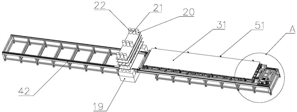
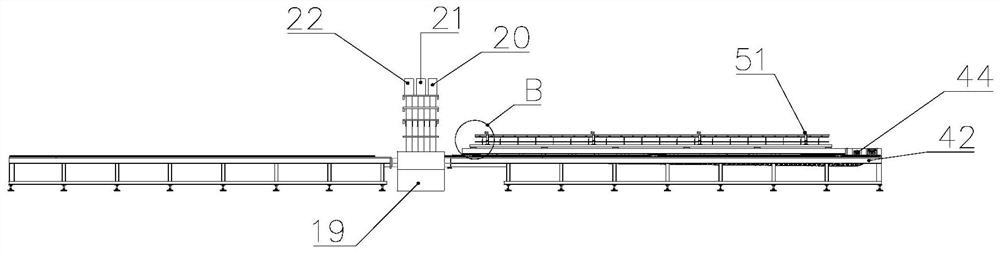
Truss 3D floor plate perforating machine
A punching machine and floor slab technology, applied in boring/drilling, drilling/drilling equipment, stone processing equipment, etc., can solve the problem of high assembly cost of steel truss floor slabs, broken drilling bits, and high damage rate. problems, to achieve the effect of improving service life, reducing breakage rate and reducing damage
- Summary
- Abstract
- Description
- Claims
- Application Information
AI Technical Summary
Problems solved by technology
Method used
Image

Examples
Embodiment approach
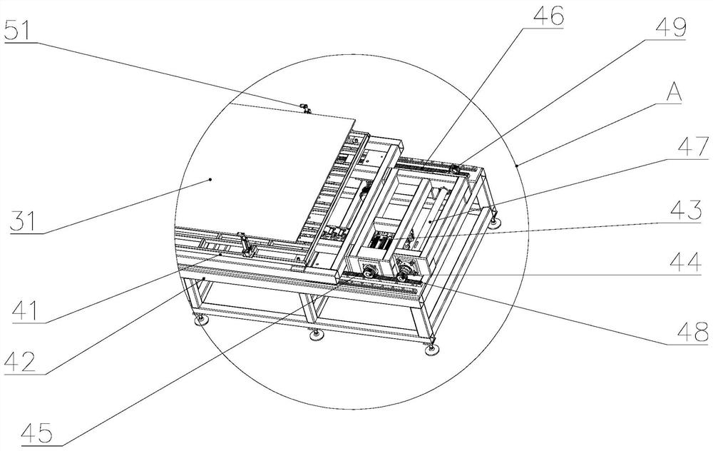
[0062] As an embodiment, the punching machine also includes a fourth drive mechanism, the fourth drive mechanism includes a power unit 43 and a main gear 44 connected to the delivery platform 41, and the first rack 45 and the first rack 45 are respectively arranged on both sides of the support beam 42. The second rack 46, the main gear 44 is meshed with the first rack 45 and / or the second rack 46; the conveying mechanism also includes a support shaft 47, and the two ends of the support shaft 47 are respectively sleeved with a first driven gear 48 and the second driven gear 49 , the first driven gear 48 is meshed with the first rack 45 , and the second driven gear 49 is meshed with the second rack 46 . By arranging the power device 43 to be connected with the conveying table 41, the main gear 44 directly drives the conveying table 41 to perform linear motion, and simultaneously the power device 43 is driven by the conveying table 41 to perform linear motion synchronously with th...
PUM
 Abstract
Description
Claims
Application Information