Distributed optical fiber detection pulse coding method based on frequency division multiplexing

A distributed optical fiber and detection pulse technology, which is applied in electromagnetic wave transmission systems, multi-carrier systems, digital transmission systems, etc., can solve problems such as low channel capacity and large loss of channel transmission performance, and achieve improved bit error performance and optimized constellation diagrams Distributing and improving the effect of channel capacity

Inactive Publication Date: 2021-06-25
CHINA COAL TECH & ENG GRP CHONGQING RES INST CO LTD +1
View PDF7 Cites 0 Cited by
  • Summary
  • Abstract
  • Description
  • Claims
  • Application Information

AI Technical Summary

Problems solved by technology

[0005] The invention provides a distributed optical fiber detection pulse coding method based on frequency division multiplexing, which solves the technical problems of large loss of channel transmission performance and low channel capacity in the prior art

Method used


Image

  • Distributed optical fiber detection pulse coding method based on frequency division multiplexing
  • Distributed optical fiber detection pulse coding method based on frequency division multiplexing

Examples


Embodiment 1

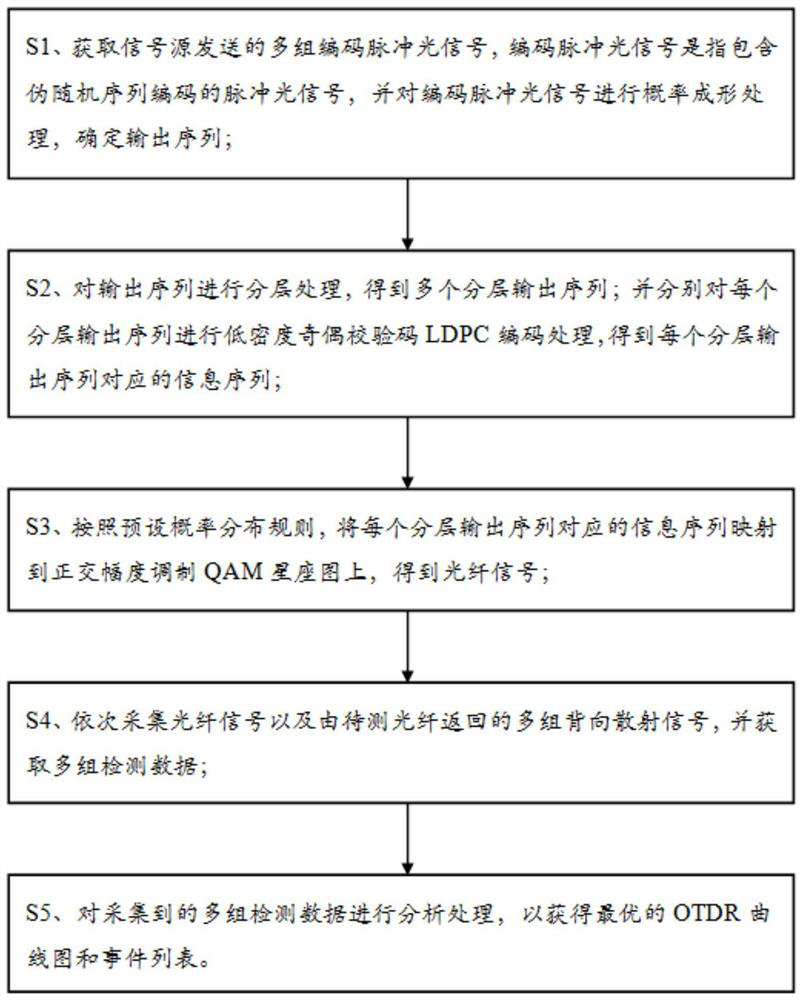
[0031] The embodiment is basically as attached figure 1 shown, including:

[0032] S1. Obtain multiple sets of coded pulsed light signals sent by the signal source. The coded pulsed light signal refers to a pulsed light signal containing a pseudo-random sequence code, and perform probabilistic shaping processing on the coded pulsed light signal to determine the output sequence;

[0033] S2. Perform hierarchical processing on the output sequence to obtain a plurality of hierarchical output sequences; and respectively perform low-density parity-check code LDPC encoding processing on each hierarchical output sequence to obtain an information sequence corresponding to each hierarchical output sequence;

[0034] S3. Map the information sequence corresponding to each layered output sequence to the quadrature amplitude modulation QAM constellation diagram according to the preset probability distribution rule to obtain the optical fiber signal;

[0035] S4. Sequentially collect optic...

Embodiment 2

[0044] The only difference from Embodiment 1 is that the optical fiber signal and multiple sets of backscattering signals returned by the optical fiber to be tested are sequentially collected, and multiple sets of detection data are obtained, specifically including the steps: the first step, a set of backscattering signals Perform light splitting to obtain a number of scattered sub-signals in different bands; the second step is to perform photoelectric conversion, amplification filtering, and analog-to-digital conversion on each scattered sub-signal to obtain a set of different types of detection data. In this way, by obtaining a number of scattering sub-signals in different bands, and then performing photoelectric conversion, amplification filtering, and analog-to-digital conversion on each of the scattering sub-signals, it is beneficial to improve the accuracy of the detection data.

Embodiment 3

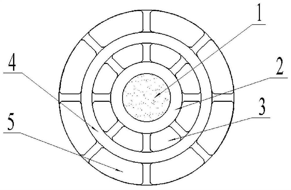
[0046] The only difference from Embodiment 2 is that in this embodiment, the optical fiber is in the open air. In some regions, due to the serious air pollution and the presence of sulfur dioxide and other gases in the air, acid rain is very likely to occur on rainy days. Typically, optical fibers are made of fiberglass material, which can corrode under the action of acid rain. The thickness of the part of the fiber corroded by acid rain will become thinner, and the reflection and refraction properties of the thinned part of the fiber will change, which will interfere with the propagation of Rayleigh light inside the fiber and eventually reduce the signal-to-noise ratio. Therefore, before modulating and demodulating the optical pulse, measures need to be taken to avoid adverse effects caused by acid rain corroding the optical fiber.

[0047] In this embodiment, a cladding layer is used to protect the optical fiber, as shown in the attached figure 2 As shown, the cladding la...


PUM


Abstract

The invention relates to the technical field of optical fiber communication, in particular to a frequency division multiplexing-based distributed optical fiber detection pulse coding method, which comprises the following steps of: S1, acquiring a plurality of groups of coded pulse optical signals sent by a signal source, and determining an output sequence; S2, performing hierarchical processing on the output sequence to obtain a plurality of hierarchical output sequences, and performing LDPC code coding processing on each layered output sequence to obtain an information sequence corresponding to each layered output sequence; S3, mapping the information sequence corresponding to each layered output sequence to a QAM constellation diagram according to a preset probability distribution rule to obtain an optical fiber signal; S4, sequentially collecting optical fiber signals and a plurality of groups of backscattering signals returned by the to-be-detected optical fiber, and obtaining a plurality of groups of detection data; S5, analyzing and processing the collected multiple groups of detection data. According to the invention, the probability shaping technology is adopted to optimize the distribution of the constellation diagram, the energy loss of optical fiber signal transmission is reduced, and the channel capacity is improved.

Description

technical field [0001] The invention relates to the technical field of optical fiber communication, in particular to a distributed optical fiber detection pulse coding method based on frequency division multiplexing. Background technique [0002] The optical time domain reflectometer (OTDR) is an instrument for measuring the transmission characteristics of optical fibers through backscattering and reflection signals. The decibel difference between) requirements are also increasing, the greater the dynamic range, the longer the fiber distance that can be measured. Due to time constraints, the dynamic range can be improved by increasing the number of accumulations, but the number of accumulations can only take a limited value; increasing the dynamic range by increasing the optical pulse width will reduce the resolution. [0003] In this regard, Chinese patent CN104048684A discloses an OTDR method based on coded pulsed optical signals, which is used to detect the optical fiber...

Claims


Application Information

Patent Timeline
Patent Type & Authority Applications(China)
IPC IPC(8): H04B10/071H04B10/524H04L1/00H04L27/34
CPCH04B10/071H04B10/524H04L1/0063H04L27/3405
Inventor 张建鑫孙维王璇孙中光戴书球钟宇张宇谭一川梁帅陶冶
Owner CHINA COAL TECH & ENG GRP CHONGQING RES INST CO LTD
Why Eureka
Try Eureka