Winding mechanism of T2 ring-shaped winding machine

A winding mechanism and winding wire technology, which is applied in the direction of coil manufacturing, conveying filamentous materials, thin material processing, etc., can solve the problem that the number of winding coils cannot be guaranteed, the coil core is difficult to install and disassemble, The structure of the winding mechanism is complicated, etc., to achieve the effect of simple structure, avoiding paint falling, and simple mechanism

Inactive Publication Date: 2021-06-29
杭州正昇安全科技有限公司
View PDF0 Cites 1 Cited by
  • Summary
  • Abstract
  • Description
  • Claims
  • Application Information

AI Technical Summary

Problems solved by technology

It contains less impurities that reduce electrical conductivity and thermal conductivity, and a trace amount of oxygen has little effect on electrical conductivity, thermal conductivity, and processing. In the processing and use of T2 copper wire, it is often necessary to process it into a coil shape, which requires the use of winding Wire machine, the winding mechanism of the traditional T2 winding machine has a complex structure and is expensive. It is difficult to install and disassemble the coil core during winding, and it lacks a pressing mechanism, which leads to the inability to guarantee the number of winding coils and the tightness and uniformity of winding. ; On the other hand, when winding, the surface of the T2 copper wire that has been stored for a long time is easy to adhere to a large amount of dust and impurities. If there is no intervention, it will affect the overall quality of the coil. Therefore, we need to propose a T2 winding machine winding mechanism

Method used


Image

  • Winding mechanism of T2 ring-shaped winding machine
  • Winding mechanism of T2 ring-shaped winding machine
  • Winding mechanism of T2 ring-shaped winding machine

Examples


Embodiment Construction

[0023] The following will clearly and completely describe the technical solutions in the embodiments of the present invention with reference to the accompanying drawings in the embodiments of the present invention. Obviously, the described embodiments are only some, not all, embodiments of the present invention. The specific embodiments described here are only used to explain the present invention, not to limit the present invention. Based on the embodiments of the present invention, all other embodiments obtained by persons of ordinary skill in the art without making creative efforts belong to the protection scope of the present invention.

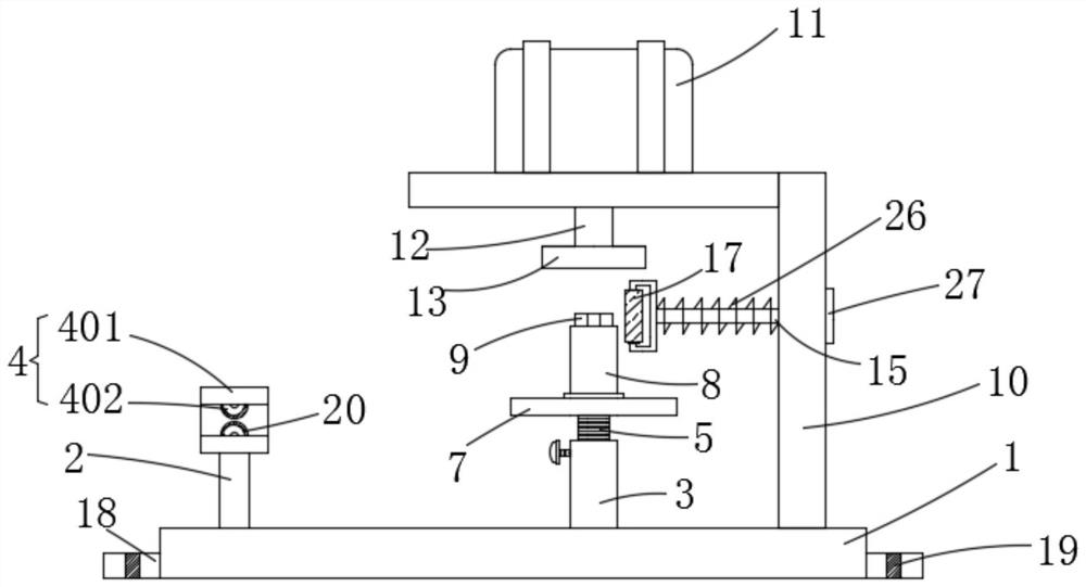
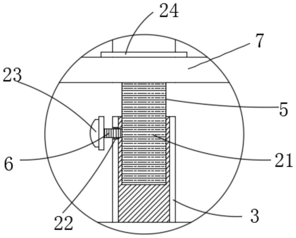
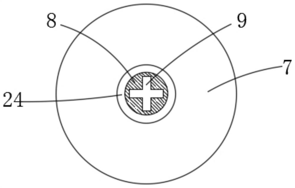
[0024] The present invention provides such Figure 1-5 The winding mechanism of a T2 winding machine shown includes a bottom plate 1, a pillar 2 and a sleeve 3 are fixedly welded on the top surface of the bottom plate 1 in sequence, and a cleaning tensioning assembly 4 is arranged on the upper end of the pillar 2, and the cleaning tension...


PUM


Abstract

The invention discloses a winding mechanism of a T2 ring-shaped winding machine. The winding mechanism comprises a baseplate, wherein a supporting column and a sleeve are fixedly welded onto the top surface of the baseplate in sequence; a cleaning and tensioning assembly is arranged at the upper end of the supporting column; a limiting column is slidably connected into the sleeve in a sleeving manner; a limiting screw rod is mounted on the side wall of the sleeve; a supporting plate is fixedly welded to the top of the limiting column; a fixing column used for fixing a coil core is arranged at the top of the supporting plate; a clamping block is arranged at the upper end of the fixing column in an integral-forming manner; a bracket is fixedly welded to one end of the surface of the baseplate; a driving motor is mounted at the top of the bracket; one end of the rotating shaft penetrates through the top of the bracket and is fixedly connected with a connecting block; a clamping groove is formed in the bottom of the connecting block; a connecting rod is slidably connected onto the side wall of the bracket in an inserting manner; a fixing frame is fixedly welded to one end of the connecting rod; and a pressing wheel is mounted on the fixing frame. The winding mechanism is high in winding efficiency and precision; the labor intensity is greatly reduced; and human resources are saved.

Description

technical field [0001] The invention belongs to the technical field of winding machine equipment, and in particular relates to a winding mechanism of a T2 winding machine. Background technique [0002] A winding machine is a device that winds a linear object onto a specific workpiece. It is usually used for copper wire winding. Most electrical products need to be wound with enamelled copper wire (enameled wire for short) to make an inductance coil. You can use a winding machine To complete this one or more processing, the wires usually wound by winding machines are mostly enamelled copper wires (winding inductance coils for electronic and electrical products), enameled aluminum wires, textile wires (winding yarns for textile machines) , coils), as well as heating wires for winding electric heating appliances, solder wires, wires, cables, etc., which are commonly used for example: various motors, coreless motors, rotors, stators, pin inductors, chip inductors, transformers, ...

Claims


Application Information

Patent Timeline
Patent Type & Authority Applications(China)
IPC IPC(8): B65H54/70B65H54/54B65H54/44H01F41/06
CPCB65H54/44B65H54/54B65H54/702B65H2701/34H01F41/06
Inventor 孙嘉聆
Owner 杭州正昇安全科技有限公司
Why Eureka
Try Eureka