Ultrasonic detection system with self-adaptive emission voltage and voltage adjusting method

A technology of self-adaptive adjustment and emission voltage, which is applied in the direction of radio wave measurement systems, measurement devices, electrical components, etc., can solve the problems of low accuracy of manual adjustment, and achieve the effect of excellent control, high signal-to-noise ratio, and easy observation

Pending Publication Date: 2021-06-29
ZHONGBEI UNIV
View PDF0 Cites 0 Cited by
  • Summary
  • Abstract
  • Description
  • Claims
  • Application Information

AI Technical Summary

Problems solved by technology

[0004] The purpose of the present invention is to provide a self-adaptive ultrasonic detection system and a voltage...

Method used


Image

  • Ultrasonic detection system with self-adaptive emission voltage and voltage adjusting method
  • Ultrasonic detection system with self-adaptive emission voltage and voltage adjusting method
  • Ultrasonic detection system with self-adaptive emission voltage and voltage adjusting method

Examples


Embodiment 1

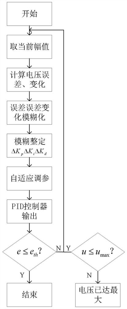
[0055] see figure 1 , an embodiment of the present invention provides a transmission voltage adaptive adjustment method of an ultrasonic testing system, the method comprising:

[0056] S1. Calculate the optimal echo voltage amplitude according to the system noise of the ultrasonic testing system and the preset expected signal-to-noise ratio;

[0057] Measure the system noise amplitude V of the ultrasonic testing system n , set the expected echo peak signal-to-noise ratio SNR, calculate the optimal echo voltage and set the attenuation multiple according to the voltage value according to the ADC voltage input amplitude range, the optimal echo voltage amplitude is V=V n .SNR; where the attenuation factor is set to ensure that the voltage amplitude range of the ADC converter is met. The amplitude of the system noise is the average value of the system noise, and the unit of the signal-to-noise ratio is times.

[0058] System noise is a kind of random noise generated by the elect...

Embodiment 2

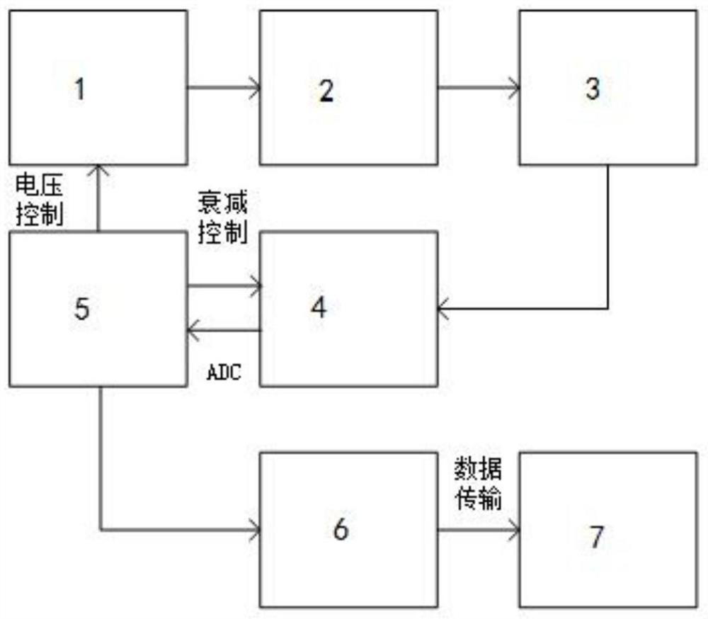
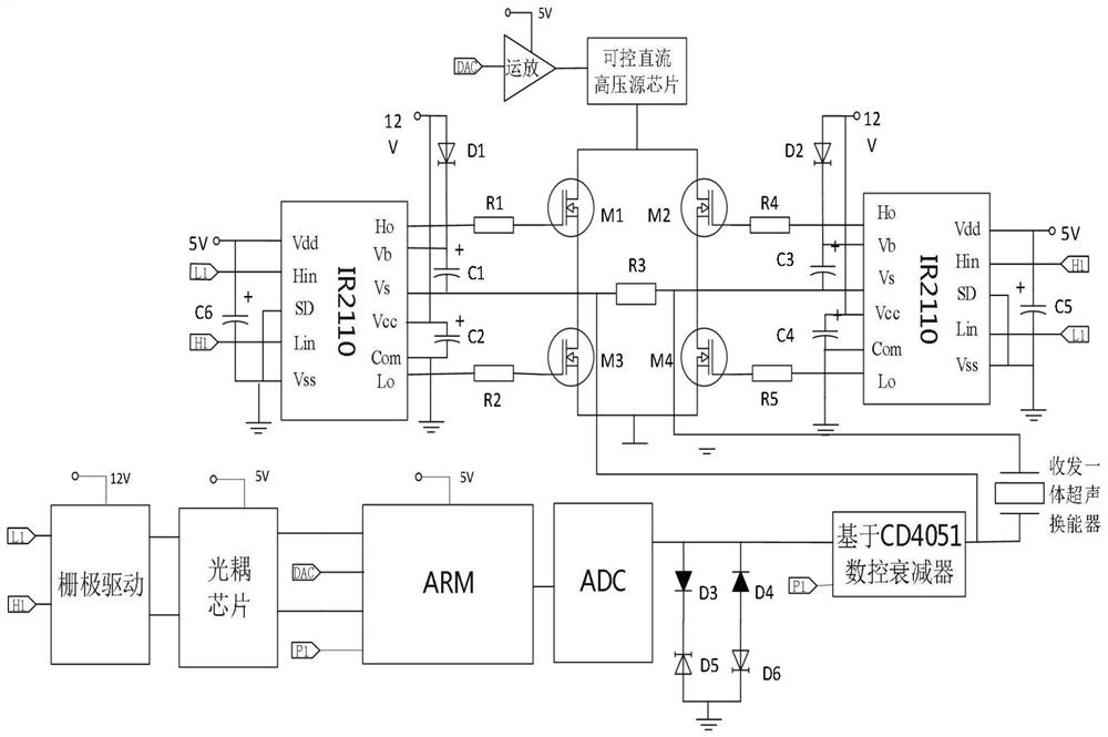
[0081] see figure 2 , the embodiment of the present invention provides an ultrasonic testing system with self-adaptive emission voltage, its specific circuit diagram is as follows image 3 As shown, the system includes:

[0082] An ultrasonic excitation power supply, an ultrasonic echo receiving circuit and a fuzzy PID controller; the fuzzy PID controller is respectively connected to the ultrasonic excitation power supply and the ultrasonic echo receiving circuit; the ultrasonic excitation power supply includes: a controllable DC high voltage source 1 and a full bridge drive circuit 2; The ultrasonic echo receiving circuit includes: a numerically controlled attenuator 4; the fuzzy PID controller includes: an ARM main control chip 5.

[0083] The ultrasonic excitation power supply is used for transmitting voltage; the transmitting voltage is adjusted by the fuzzy PID controller; the ultrasonic echo receiving circuit is used for collecting echo signals; the echo signal is the ...


PUM


Abstract

The invention relates to an ultrasonic detection system with self-adaptive emission voltage and a voltage regulation method. The method includes design of a numerical control bipolar ultrasonic excitation power supply, design of an ultrasonic echo receiving circuit and design of a fuzzy self-tuning PID control scheme. The method comprises the steps of setting an optimal ultrasonic echo signal amplitude according to system noise and an expected echo peak signal-to-noise ratio, setting a corresponding attenuation multiple, collecting the amplitude of an echo signal, calculating an error and an error change rate, carrying out fuzzy reasoning by using a fuzzy rule, searching a fuzzy rule table to carry out adjustment on parameters Kp, Ki and Kd, controlling the emission voltage of the numerical control bipolar ultrasonic excitation power supply according to the control quantity obtained by the PID controller, and providing an ultrasonic echo signal with a high signal-to-noise ratio and a stable amplitude for subsequent signal processing.

Description

technical field [0001] The invention relates to the field of ultrasonic detection, in particular to an ultrasonic detection system and a voltage adjustment method with self-adaptive emission voltage. Background technique [0002] Ultrasonic nondestructive testing technology is the most widely used detection technology among the five conventional detection technologies, which has the advantages of high emission voltage and good directivity. With the development and progress of ultrasonic testing technology, ultrasonic testing equipment has also been updated, but the degree of intelligence of ultrasonic testing equipment at home and abroad is still relatively low. As far as digital ultrasonic testing products are concerned, the driving voltage of ultrasonic testing engineering needs to be manually adjusted by technicians according to the amplitude of the ultrasonic echo. This is a rough adjustment. High power consumption. Especially for portable ultrasonic detectors, excessi...

Claims


Application Information

Patent Timeline
IPC IPC(8): G01S15/88H02M1/092G05B11/42
CPCG01S15/88G05B11/42H02M1/092
Inventor 庞存锁张硕韩焱王黎明贤光聂鹏飞
Owner ZHONGBEI UNIV
Why Eureka
Try Eureka