Steel wheel heat treatment system and method

A heat treatment system and heat treatment method technology, applied in the field of steel wheel heat treatment system, can solve the problems of quenching medium pollution, wheel deformation, affecting quenching and heat preservation effects, etc.

Pending Publication Date: 2021-07-02
BEIJING RES INST OF MECHANICAL&ELECTRICAL TECH +1
View PDF0 Cites 1 Cited by
  • Summary
  • Abstract
  • Description
  • Claims
  • Application Information

AI Technical Summary

Problems solved by technology

[0003] At present, the Q&P heat treatment process is difficult to apply in industry. In industry, salt bath, quenching oil, temperature control mold and other methods are used to realize quenching and heat preservation. However, the risk factor of salt bath and quenching oil is high, and industrial application will produce a lot of pollution. Increase the follow-up processing procedure and cost, the manufacturing cost of the temperature control mold is high, and the requirements on the shape of the parts are high. The above methods are not conducive to the mass production of complex structural parts such as steel wheels. Joints tend to create quench dead spots, resulting in poor performance in this area, which adversely affects steel wheel service performance
Or the welding seam is not uniformly quenched. Due to the large residual stress at the weld seam, it may cause the weld seam to crack and the wheel to deform
At the same time, salt bath and quenching oil are more sensitive to the external environment. Long-term use will pollute the quenching medium and affect the effect of quenching and heat preservation. It is difficult to replace the quenching medium.

Method used


Image

  • Steel wheel heat treatment system and method
  • Steel wheel heat treatment system and method
  • Steel wheel heat treatment system and method

Examples


Embodiment Construction

[0031] Below, the specific structure and layout of the steel wheel heat treatment system of the present application will be described in detail with reference to the accompanying drawings.

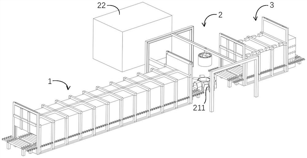
[0032] figure 1 It is a schematic diagram of the distribution of the steel wheel heat treatment system of the present application. Such as figure 1 As shown, the steel wheel heat treatment system of the present application includes: the first heating furnace 1 (roller hearth heating furnace in the figure, can also adopt forms such as walking heating furnace), cooling device 2, second heating furnace 3 (figure The middle is a roller hearth heating furnace, and a walking heating furnace can also be used) in three parts. Among them, the first heating furnace 1 is used to heat the steel wheel, so that the inner structure of the steel wheel is completely transformed into austenite; The steel wheel is uniformly cooled by a controllable jet flow, so that the cooling rate of each part of the st...


PUM


Abstract

The invention provides a steel wheel heat treatment system and method. The steel wheel heat treatment system comprises a first heating furnace, a jet cooler and a second heating furnace, wherein the first heating furnace is used for heating a steel wheel to enable the steel wheel to be completely austenitized; the jet cooler can be used for jetting a cooling medium to the surface of the steel wheel to enable the steel wheel to be quickly cooled to 100-400 DEG C at the cooling speed of 5 DEG C/s or above; and the second heating furnace is used for heating the steel wheel to enable the temperature of the steel wheel to be kept at 250-400 DEG. By adopting the system, the steel wheel is quenched by jetting the cooling medium to the surface of the steel wheel. The cooling medium obtained after the steel wheel is quenched cannot pollute or affect the newly-jetted cooling medium, and the cooling medium can be replaced conveniently. Thus, the production cost is reduced, and Q and P heat treatment of the steel wheel is suitable for large-scale production.

Description

technical field [0001] The invention relates to the technical field of heat treatment, in particular to a steel wheel heat treatment system and method. Background technique [0002] Under the background of automobile lightweight, the replacement of traditional automobile steel by the third generation of advanced high strength steel (AHSS) can reduce the weight by about 20%. At the same time, based on the safety of automotive structural parts, AHSS for automobiles is required to have excellent comprehensive mechanical properties, good impact energy absorption characteristics, and the strength-plastic product must reach a level above 20.0GPa·%. This requires the material to maintain high strength but also have good shape and toughness. The Q&P (Quenching and Partitioning, quenching-redistribution) heat treatment process based on the austenite TRIP effect and the α / γ multiphase structure theory can make the ultra-high-strength steel for traditional hot forming have a good stre...

Claims


Application Information

Patent Timeline
Patent Type & Authority Applications(China)
IPC IPC(8): C21D1/62C21D1/667C21D6/00C21D9/34
CPCC21D1/62C21D1/667C21D6/00C21D9/0025C21D9/0062C21D9/34C21D2211/001C21D2211/008
Inventor 李贤君徐冬雁符浩韩忠娣
Owner BEIJING RES INST OF MECHANICAL&ELECTRICAL TECH
Why Eureka
Try Eureka