
Pre-ignition chamber fuel supply system and engine

A technology of fuel supply system and pre-combustion chamber, which is applied in the direction of combustion engine, internal combustion piston engine, machine/engine, etc. It can solve the problems of increased uncertainty of flame development, difficulty in cold start, and large engine cycle changes, so as to avoid coking and soot generation, improve ignition stability, and reduce the risk of leakage

Inactive Publication Date: 2021-07-02
GUANGZHOU AUTOMOBILE GROUP CO LTD
View PDF6 Cites 0 Cited by
  • Summary
  • Abstract
  • Description
  • Claims
  • Application Information

AI Technical Summary

Problems solved by technology

Gasoline engine active pre-chamber auxiliary enrichment usually adopts gasoline direct injection method, but the direct injection enrichment method has the following disadvantages: 1. Due to the small volume of the pre-combustion chamber, the direct injection method causes serious fuel collision with the wall, which is easy to coke and generate carbon Smoke; 2. The stability of the fuel concentration at the spark plug position is poor, resulting in increased uncertainty in flame development and large engine cycle changes; 3. In order to overcome the disadvantage 2, it is necessary to correct and adjust the fuel injection timing and injection quantity, and the control logic More complicated; 4. Gasification and heat absorption in the pre-combustion chamber after gasoline direct injection makes cold start more difficult

Method used


Image

  • Pre-ignition chamber fuel supply system and engine
  • Pre-ignition chamber fuel supply system and engine
  • Pre-ignition chamber fuel supply system and engine

Examples


Embodiment Construction

[0028] The specific implementation manners of the present invention will be further described in detail below in conjunction with the accompanying drawings and embodiments. The following examples are used to illustrate the present invention, but are not intended to limit the scope of the present invention.

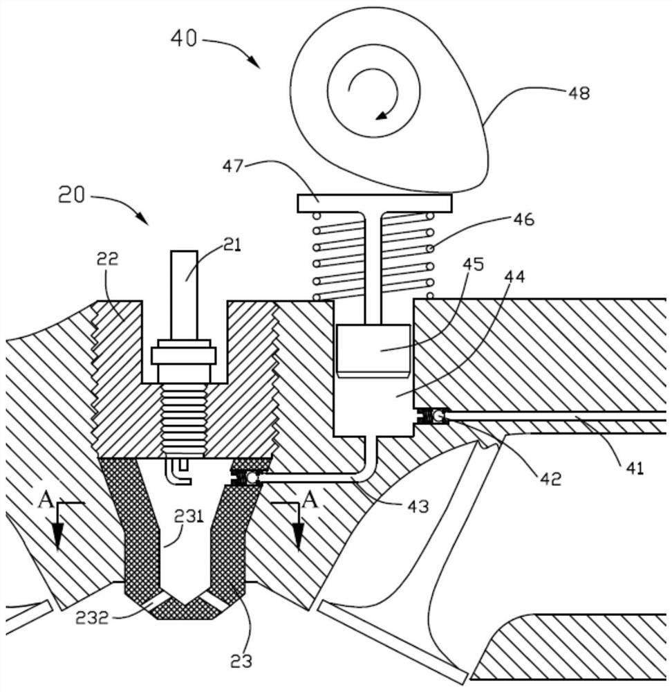
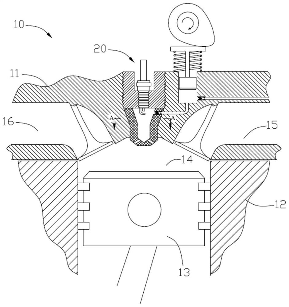
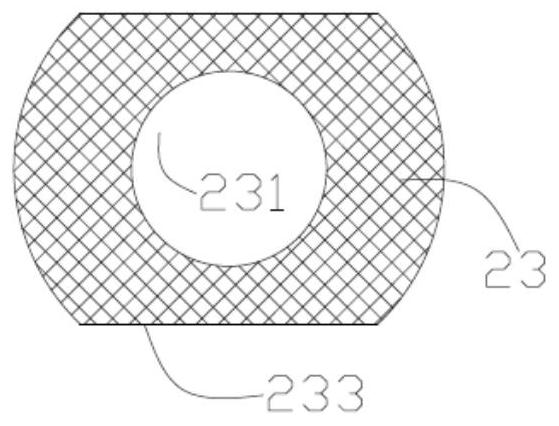
[0029] Please refer to Figure 1 to Figure 5 , the pre-chamber fuel supply system of the embodiment of the present invention is used for the engine 10, including the pre-chamber device 20 and the air intake device, the front end of the air intake device communicates with the throttle valve 51, the rear end communicates with the pre-chamber device 20, and the pre-combustion chamber The chamber device 20 communicates with the engine 10 . The intake device includes an intake pipe 52 , a first compression device 53 , a gasification mixing device 54 , a second compression device 40 and a pre-chamber check valve 30 . The intake pipe 52 communicates with the first compression d...


PUM


Abstract

The invention discloses a pre-ignition chamber fuel supply system and an engine with the pre-ignition chamber fuel supply system. The pre-ignition chamber fuel supply system comprises a pre-ignition chamber device and an air inlet device; the air inlet device is communicated with the pre-ignition chamber device; the pre-ignition chamber device is communicated with the engine; the air inlet device comprises an air inlet pipeline and a gasification mixing device used for gasifying and mixing fuel oil and air flowing in from the air inlet pipeline; and the air inlet pipeline penetrates through the gasification mixing device to be communicated with the pre-ignition chamber device. The pre-ignition chamber adopts a pre-mixing mode, so that the equivalence ratio of the ignition position of the pre-ignition chamber is easier to guarantee, the mixing quality is improved, and coking and soot generation caused by too thick mixed gas are avoided. The high-pressure mixed gas is prepared when used, a high-pressure gas storage device is omitted, the temperature of the compressed mixed gas is increased, and the ignition stability is further improved. After a throttle valve is selected at the air inlet position, the preparation amount of the mixed gas may be in direct proportion to the load of the engine, and no or only a simple electric control device is required.

Description

technical field [0001] The invention relates to the field of automobile engines, in particular to a pre-combustion chamber fuel supply system. Background technique [0002] With the increasingly stringent emission regulations and fuel consumption regulations, more severe challenges are posed to the existing gasoline engine technology. Improving the thermal efficiency of gasoline engines and reducing fuel consumption have always been the goals pursued by major manufacturers. Lean burn is one of the effective ways to improve the thermal efficiency of gasoline engine. Existing experimental data show that gasoline engines adopt mild lean combustion (the excess air coefficient (lambda) is between 1 and 1.5), which can improve thermal efficiency, but at this time, due to deviation from the theoretical air-fuel ratio, the three-way catalytic converter cannot be used. Expensive NOx aftertreatment equipment is required to meet emission regulations. If ultra-lean combustion (lambda...

Claims


Application Information

Patent Timeline
IPC IPC(8): F02B19/10
CPCF02B19/109Y02T10/12
Inventor 韦静思许汉君刘明嘉武珊马桂香袁懋荣陈泓周昭求
Owner GUANGZHOU AUTOMOBILE GROUP CO LTD
Learn More