Novel low-pollution bubbling bed gasification combustion reaction device and method

A combustion reaction, low-pollution technology, applied in combustion methods, combustion types, incinerators, etc., can solve the problems of large ash production, large fluctuations in pressure drop in bubbling fluidized bed, and high exhaust gas treatment costs, and achieves high Effects of combustion heat load, rapid heat and mass transfer, NOx reduction

Inactive Publication Date: 2021-07-02
DALIAN UNIV OF TECH
View PDF6 Cites 0 Cited by
  • Summary
  • Abstract
  • Description
  • Claims
  • Application Information

AI Technical Summary

Problems solved by technology

Burning it directly will produce a large amount of SO due to high local temperature x , NO x , fly ash and heavy metal pollution, the result is that the cost of tail gas treatment is extremely high, how to remove pollutants in the device is the key to solving this problem
[0003] For organic solid particles, the ideal combustion device is a fluidized bed structure. The fluidized bed includes aggregate fluidization and diffuse fluidization. The fluidization process of the diffuse fluidization is relatively uniform, and the particles are evenly distributed. The widely used circulating fluidized bed has uneven particle distribution and large bubble-like voids in the particles. It is also called bubbling fluidized bed. The height of conventional circulating fluidized bed is high and the ash production is large. , The pressure drop of conventional bubbling fluidized bed fluctuates greatly, and the contact between gas and solid is not good

Method used


Image

  • Novel low-pollution bubbling bed gasification combustion reaction device and method

Examples


Embodiment

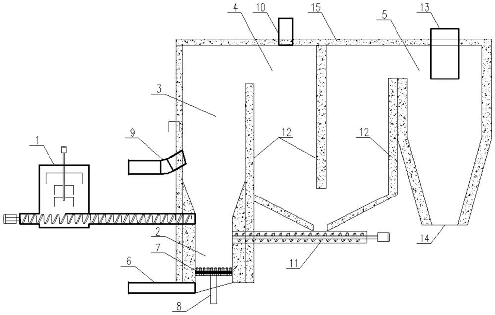
[0028] The organic solid particles and desulfurizer are sent into the bubbling gasification section 2 through the feeding device 1, and gasification reaction occurs after contacting the air from the gasification medium inlet 6 to generate gasification gas and ash, and the gasification gas is sent to the second gasification section. In the combustion section 3, the ash and slag are discharged through the slag discharge device 8; during the whole gasification reaction process, the organic solid particles are in the state of rapid fluidization and bubbling fluidization, and the gasification temperature is maintained between 500-800°C. Most of the sulfur contained in the solid particles will remain in the ash; the gasification gas from the bubbling gasification section 2 and the air from the secondary combustion medium inlet 9 are fully mixed in the secondary combustion section 3, and a low-temperature low-oxygen combustion reaction occurs During the combustion process, the total g...


PUM


Abstract

The invention discloses a novel low-pollution bubbling bed gasification combustion reaction device and method. The device comprises a feeding device, a bubbling gasification section, a second-stage combustion section, a last-stage combustion section and a cyclone separation device. Organic solid particles are fed into the bubbling gasification section through the feeding device, meanwhile, air is introduced to make contact with the organic solid particles for a gasification reaction, gasified gas and ash are generated, the gasified gas is sequentially fed into the second-stage combustion section and the last-stage combustion section and fully mixed with the air for a low-oxygen combustion reaction, flue gas is formed, solid particles which are not completely reacted and mixed in the flue gas are isolated by a dust isolation plate and fall to the bottom of the last-stage combustion section, the solid particles are conveyed to the bubbling gasification section through a high-temperature mechanical material returning device to be subjected to gasification reaction again, and the remaining flue gas is conveyed into the cyclone separator to be subjected to dust removal again and then conveyed into a subsequent energy recovery and flue gas treatment system. On the premise of meeting the combustion heat efficiency of the organic solid particles, the generation amount of NOx, SOx and fly ash can be greatly reduced, the height of the furnace body is reduced, and then the follow-up investment and operation cost are reduced.

Description

technical field [0001] The invention belongs to the technical field of energy utilization and environmental protection, and in particular relates to a novel low-pollution bubbling bed gasification combustion reaction device and method. Background technique [0002] There are many types of organic matter and the yield is huge. Burning it directly will produce a large amount of SO due to high local temperature x , NO x , fly ash and heavy metal pollution, the result is that the cost of tail gas treatment is extremely high, how to realize the removal of pollutants in the device is the key to solving this problem. [0003] For organic solid particles, the ideal combustion device is a fluidized bed structure. The fluidized bed includes aggregate fluidization and diffuse fluidization. The fluidization process of the diffuse fluidization is relatively uniform, and the particles are evenly distributed. The widely used circulating fluidized bed has uneven particle distribution and...

Claims


Application Information

Patent Timeline
Patent Type & Authority Applications(China)
IPC IPC(8): F23G5/027F23G5/14F23G5/44F23G5/46F23G5/50
CPCF23G5/027F23G5/14F23G5/44F23G5/444F23G5/46F23G5/50
Inventor 李爱民王欣张雷侯大明姬国钊赵紫宁高原
Owner DALIAN UNIV OF TECH
Why Eureka
Try Eureka