Post-welding rapid cooling equipment for high-end equipment manufacturing

A post-welding and equipment technology, which is applied in the field of rapid cooling equipment after welding for high-end equipment manufacturing, can solve the problems of inability to flexibly control the cooling range, large loss, and low welding strength

Active Publication Date: 2021-07-06
山东北易车业有限公司
View PDF6 Cites 1 Cited by
  • Summary
  • Abstract
  • Description
  • Claims
  • Application Information

AI Technical Summary

Problems solved by technology

[0004] In order to overcome the shortcomings of low welding strength, inability to flexibly control the cooling range, and high loss, the purpose of the present invention is to provide a sealing assembly with good temperature control effect,

Method used


Image

  • Post-welding rapid cooling equipment for high-end equipment manufacturing
  • Post-welding rapid cooling equipment for high-end equipment manufacturing
  • Post-welding rapid cooling equipment for high-end equipment manufacturing

Examples


Embodiment 1

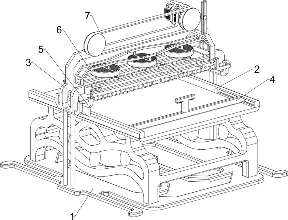
[0028] A rapid cooling equipment after welding for high-end equipment manufacturing, such as Figure 1-Figure 4 As shown, it includes a base 1 , a placement component 2 and a sprinkling component 3 . The top of the base 1 is provided with a placement component 2 , and the top of the base 1 is provided with a sprinkling component 3 .

[0029] People place the welded high-temperature metal on the placement component 2, and move the sprinkler component 3 to spray water to cool the high-temperature metal, so as to achieve the effect of simple structure and convenient operation.

[0030] The placement assembly 2 includes a first support frame 21, a placement plate 22 and a baffle plate 23. The top of the base 1 is provided with a first support frame 21, and the top of the first support frame 21 is provided with a placement plate 22. Baffle 23.

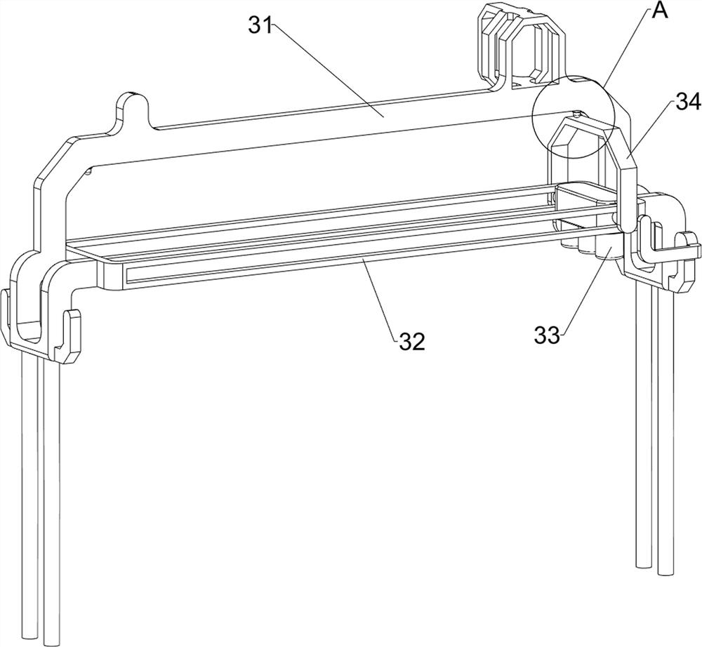
[0031] The sprinkler assembly 3 includes a second support frame 31, a first slide rail 32, a sprinkler head 33, a first connecting rod 34...

Embodiment 2

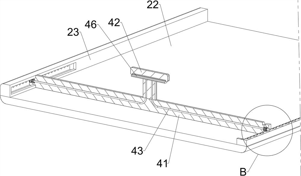
[0034] On the basis of Example 1, such as Figure 5-Figure 9 As shown, a positioning assembly 4 is also included, and the positioning assembly 4 includes a blocking rod 41, a handle 42, a stay cord 43, a second connecting rod 44, a first spring 45 and a third connecting rod 46, and the front side of the top of the blocking plate 23 The sliding type is provided with stop bar 41, and the top of stop bar 41 is provided with handle 42, and the sliding type on handle 42 is provided with the 3rd connecting rod 46, and the left and right symmetrical sliding type of stop bar 41 is provided with the second connecting rod 44, and Sliding fit between the second connecting rod 44 and the baffle plate 23, a pull cord 43 is connected between the second connecting rod 44 and the third connecting rod 46, and a first connecting rod 44 is connected with the blocking rod 41. Spring 45.

[0035] When people need to cool down the high-temperature metal, the third connecting rod 46 on the lower si...


PUM


Abstract

The invention relates to cooling equipment, in particular to post-welding rapid cooling equipment for high-end equipment manufacturing. The invention aims to provide the post-welding rapid cooling equipment for high-end equipment manufacturing. The post-welding rapid cooling equipment has a good temperature control effect, improves the welding strength through point cooling, reduces the loss, effectively protects a sealing assembly in a welding part, and does not influence the quality of a welding seam. The invention discloses post-welding rapid cooling equipment for high-end equipment manufacturing. The post-welding rapid cooling equipment comprises a base, a placing assembly, a watering assembly and the like; and the top of the base is provided with the placing assembly and the watering assembly, and the watering assembly is located at the top of the placing assembly. A first connecting rod makes contact with a right button for the first time, a spray head is opened, high-temperature metal begins to be cooled, when the first connecting rod makes contact with a left button, the contact is the second contact, and therefore the spray head is closed.

Description

technical field [0001] The invention relates to a cooling device, in particular to a rapid cooling device after welding for high-end equipment manufacturing. Background technique [0002] The early welding was a forging method in which two pieces of metal were heated to a low-melting point tin-lead alloy with a fire soldering iron, and then heated to a red hot state and connected together by forging. At present, the product of modern industry brought about by the rapid development of electronic industry technology, welding technology has penetrated into various fields of manufacturing industry, metal processing composed of welding and metal cutting processing, pressure processing, casting, heat treatment, cooling and other methods Technology has become the basic means of production in various industries such as automobiles, ships, aircraft, aerospace, atomic energy, petroleum, chemical industry, electronics, etc., and directly affects product quality, reliability, life, prod...

Claims


Application Information

Patent Timeline
IPC IPC(8): B23K37/00
CPCB23K37/003Y02P70/10
Inventor 朱尚富
Owner 山东北易车业有限公司
Why Eureka
Try Eureka