Intelligent unmanned aerial vehicle

A kind of unmanned aerial vehicle, intelligent technology, applied in the field of unmanned aerial vehicles, can solve problems such as troubles, shortened flight time of unmanned aerial vehicles, unstable unmanned aerial vehicle bodies, etc.

Active Publication Date: 2021-07-06
INST OF ENVIRONMENT & SUSTAINABLE DEV IN AGRI CHINESE ACADEMY OF AGRI SCI
View PDF7 Cites 1 Cited by
  • Summary
  • Abstract
  • Description
  • Claims
  • Application Information

AI Technical Summary

Problems solved by technology

[0004] First, one of the key technical points of intelligent drones used in plant protection work is the issue of battery life. Compared with ordinary visual drones, drones used in plant protection work also need to add a separate power pump system , to spray the water medicine, the operation of the power pump system needs to consume energy, resulting in a greatly shortened flight time of the drone
[0005] Second, intelligent drones need to carry a spraying box for plant protection work. When working in a low-temperature environment and area, the water in the water tank will be in a semi-solidified state, resulting in uneven distribution when spraying and discharging
[0006] Third, when intelligent UAVs are used in plant protection work, they not only need to spray liquid substances, but also spray granular substances. Existing UAVs need to replace different spraying mechanisms when spraying different substances, which is more troublesome
[0007] Fourth, when the smart UAV stops or turns while carrying a box containing water medicine, the water medicine will shake in the box, causing the body of the drone to be unstable, and additional energy will be consumed during the balance adjustment process
[0008] Fifth, the intelligent UAV used in plant protection work often needs to refuel or add medicine multiple times in one job. This part of the work requires manual operation, which is more troublesome

Method used


Image

  • Intelligent unmanned aerial vehicle
  • Intelligent unmanned aerial vehicle
  • Intelligent unmanned aerial vehicle

Examples


Embodiment 1

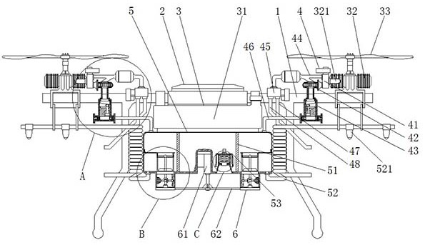
[0056] The present invention provides an intelligent unmanned aerial vehicle through improvement, such as Figure 1-Figure 17 As shown, a kind of intelligent unmanned aerial vehicle comprises frame 1, and described frame 1 is provided with flight control system 2, power system 3 and spray box 5, and wherein power system 3 comprises fuel tank 31, several engines 32 and rotor 33, several gas energy utilization components 4 are installed on the frame 1, the gas energy utilization components 4 are connected to the exhaust pipe 321 of the engine 32, and the gas energy utilization components 4 are connected to the spray box 5, and the gas energy utilization components 4 is connected with the liquid spray pipe 52 on one side of the spray box 5. The bottom of the spray box 5 is provided with a self-closing liquid filling port assembly 53, and the bottom of the spray box 5 is provided with a pneumatic rotary sprinkler assembly 6.

[0057] The flow kinetic energy and temperature heat en...

Embodiment 2

[0065] The present invention provides an intelligent unmanned aerial vehicle through improvement, such as Figure 1-Figure 17 As shown, a kind of intelligent unmanned aerial vehicle comprises frame 1, and described frame 1 is provided with flight control system 2, power system 3 and spray box 5, and wherein power system 3 comprises fuel tank 31, several engines 32 and rotor 33, several gas energy utilization components 4 are installed on the frame 1, the gas energy utilization components 4 are connected to the exhaust pipe 321 of the engine 32, and the gas energy utilization components 4 are connected to the spray box 5, and the gas energy utilization components 4 is connected with the liquid spray pipe 52 on one side of the spray box 5. The bottom of the spray box 5 is provided with a self-closing liquid filling port assembly 53, and the bottom of the spray box 5 is provided with a pneumatic rotary sprinkler assembly 6.

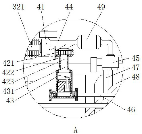
[0066]The gas energy utilization assembly 4 includes a...

Embodiment 3

[0071] The present invention provides an intelligent unmanned aerial vehicle through improvement, such as Figure 1-Figure 17 As shown, a kind of intelligent unmanned aerial vehicle comprises frame 1, and described frame 1 is provided with flight control system 2, power system 3 and spray box 5, and wherein power system 3 comprises fuel tank 31, several engines 32 and rotor 33, several gas energy utilization components 4 are installed on the frame 1, the gas energy utilization components 4 are connected to the exhaust pipe 321 of the engine 32, and the gas energy utilization components 4 are connected to the spray box 5, and the gas energy utilization components 4 is connected with the liquid spray pipe 52 on one side of the spray box 5. The bottom of the spray box 5 is provided with a self-closing liquid filling port assembly 53, and the bottom of the spray box 5 is provided with a pneumatic rotary sprinkler assembly 6.

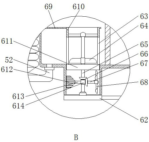
[0072] One side of the bottom of the spray box 5 is pr...


PUM


Abstract

The invention provides an intelligent unmanned aerial vehicle, which comprises a rack, a flight control system, a power system and a spraying box are arranged on the rack, the power system comprises an oil tank, a plurality of engines and rotor wings, a plurality of gas energy utilization assemblies are installed on the rack, and the gas energy utilization assemblies are connected with exhaust pipes of the engines. The gas energy utilization assemblies are connected with the spraying box, each gas energy utilization assembly is connected with a liquid spraying pipe on one side of the spraying box in a matched mode, a self-sealing liquid adding opening assembly is arranged at the bottom of the spraying box, and a pneumatic rotating scattering assembly is arranged at the bottom of the spraying box. According to the device, flowing kinetic energy and temperature heat energy of tail gas exhausted by the engine can be utilized at the same time through the gas energy utilization assembly, the flowing kinetic energy of the tail gas can be converted into power for pressurizing the spraying box, the temperature heat energy of the tail gas can preheat liquid medicine before spraying, and active spraying power and a heating mechanism do not need to be arranged; the energy consumption can be greatly reduced, and the unmanned aerial vehicle has longer endurance in plant protection work.

Description

technical field [0001] The invention relates to the technical field of unmanned aerial vehicles, in particular to an intelligent unmanned aerial vehicle. Background technique [0002] Unmanned aircraft, referred to as "UAV", is an unmanned aircraft controlled by radio remote control equipment and its own program control device. There is no cockpit on board, but equipment such as autopilot and program control device are installed. The personnel on the ground, on the ship, or at the remote control station of the parent aircraft track, locate, remotely control, telemeter and digitally transmit it through radar and other equipment. Under the radio control, it can take off like an ordinary aircraft or be launched into the air with a booster rocket, and it can also be taken into the air by the parent aircraft for flight. When recovering, it can automatically land in the same way as the common aircraft landing process, and can also be recovered by remote control with a parachute ...

Claims


Application Information

Patent Timeline
Patent Type & Authority Applications(China)
IPC IPC(8): B64D1/18B64C27/08A01M7/00A01C17/00
CPCB64D1/18B64C27/08A01M7/0042A01C17/005A01C17/003A01M7/0085B64U10/10B64U2101/00
Inventor 王耀生郝卫平冯良山杨宁马海洋
Owner INST OF ENVIRONMENT & SUSTAINABLE DEV IN AGRI CHINESE ACADEMY OF AGRI SCI
Why Eureka
Try Eureka