Durable dew-blocking-prevention combined-type exhaust gas waste heat utilization device

A flue gas waste heat, combined technology, used in steam generation methods using heat carriers, indirect heat exchangers, climate sustainability, etc., can solve problems such as personnel and property losses, safety hazards, leakage, etc. The effect of corrosion, avoidance of aggregation, and prevention of low temperature condensation of flue gas

Active Publication Date: 2015-07-15
JIANGSU WISDOM ENG TECH
View PDF8 Cites 0 Cited by
  • Summary
  • Abstract
  • Description
  • Claims
  • Application Information

AI Technical Summary

Problems solved by technology

Although this type of boiler can effectively recover the heat in the flue gas, there is still the possibility of leakage. Once the heat transfer oil on the cold side comes into direct contact with the flue gas on the hot side, there is a danger of explosion at any time, resulting in loss of personnel and property. Bigger security risk

Method used


Image

  • Durable dew-blocking-prevention combined-type exhaust gas waste heat utilization device
  • Durable dew-blocking-prevention combined-type exhaust gas waste heat utilization device

Examples


Embodiment 1

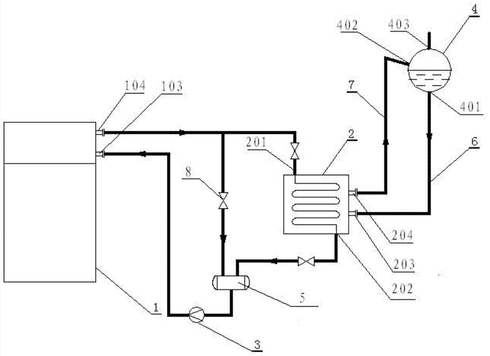
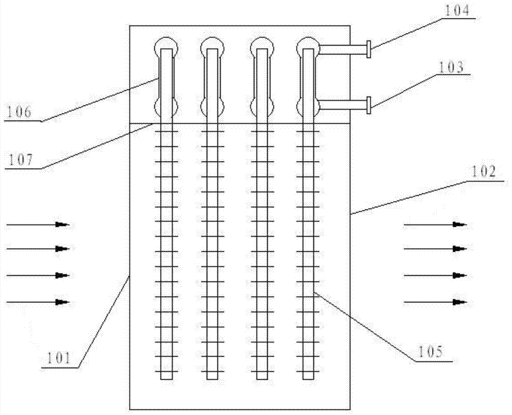
[0031] As shown in the figure, this embodiment provides a durable anti-dew combined flue gas waste heat utilization device, including heat transfer oil casing heat pipe heat exchanger 1, tube heat exchanger 2, heat transfer oil pump 3, steam drum 4 and The expansion tank 5, the lower end of the heat transfer oil jacketed heat pipe heat exchanger 1 is provided with a flue gas inlet 101 and the flue gas outlet 102, and the upper end of the heat transfer oil jacketed heat pipe heat exchanger 1 is provided with a heat transfer oil inlet I 103 and a heat transfer oil outlet I 104, The heat transfer oil inlet I103 is connected to the outlet of the heat transfer oil pump 3 , and the inlet of the heat transfer oil pump 3 is connected to the outlet of the expansion tank 5 .

[0032] Tubular heat exchanger 2 is divided into hot side and cold side. The hot side of tube heat exchanger 2 is provided with heat transfer oil inlet II 201 and heat transfer oil outlet II 202. The cold side of tu...

Embodiment 2

[0036] This embodiment is used in the production process of titanium dioxide, and the calcination process will produce a large amount of tail gas for recycling. This embodiment uses the same equipment as in Example 1, and the calcination process produces a large amount of tail gas from the heat transfer oil casing. The flue gas inlet 101 of the type heat pipe heat exchanger 1 enters, and is discharged from the flue gas outlet 102 after the countercurrent heat exchange occurs with the heat pipe working fluid in the heat conduction oil jacketed heat pipe heat exchanger 1 .

[0037] The working process of this embodiment is: after the calcination process produces a large amount of tail flue gas through the heat-conducting oil casing heat pipe heat exchanger 1, the heat of the medium and high temperature flue gas is transferred to the tube heat exchanger 2 by means of heat transfer. Oil, after the oil temperature rises, the heat is transferred to the water in the steam drum 4 by me...


PUM


Abstract

The invention discloses a durable dew-blocking-prevention combined-type exhaust gas waste heat utilization device which comprises a conduction oil casing type heat pipe exchanger, a pipe heat exchanger, a conduction oil pump, a steam pocket and an expansion groove. The expansion groove is provided with two inlets and an outlet. A conduction oil outlet formed in the conduction oil casing type heat pipe exchanger is connected with a conduction oil inlet formed in the pipe heat exchanger through a conduction oil pipeline. A conduction oil outlet formed in the pipe heat exchanger is connected with the first inlet of the expansion groove through a conduction oil pipeline. The outlet of the expansion groove is connected with a conduction oil inlet formed in the conduction oil casing type heat pipe exchanger through the conduction oil pump. A conduction oil bypass pipe is connected between the front end of the conduction oil inlet of the pipe heat exchanger and the second inlet of the expansion groove. A cooling water outlet II formed in the steam pocket is connected with a cooling water inlet I formed in the pipe heat exchanger. A steam outlet I formed in the pipe heat exchanger is connected with a steam inlet II formed in the steam pocket. Generated steam is provided for a user through a steam outlet of the steam pocket.

Description

technical field [0001] The invention belongs to a waste heat utilization device, in particular to a durable anti-dew blocking combined flue gas waste heat utilization device. Background technique [0002] During the operation of the factory, a large amount of medium-high temperature dusty flue gas will be produced, and the flue gas contains a large amount of sensible heat. In order to reduce energy consumption, achieve optimal utilization of resources, and meet air pollutant emission requirements, waste heat recovery systems are usually used to recover waste heat from flue gas and generate steam or hot water to meet production and living needs. [0003] At present, the heat exchangers in domestic waste heat recovery systems are basically finned tube or heat pipe heat exchangers. When recovering medium-high temperature flue gas with high dust content and high sulfur content, the dew point temperature of the flue gas is generally high, which can reach above 200°C, especially ...

Claims


Application Information

Patent Timeline
Patent Type & Authority Patents(China)
IPC IPC(8): F22B1/18F22B31/08F22B35/00F28D15/02
CPCY02P80/15
Inventor 李来所朱瑞贺江厚月梁正华周杰刘宇浩
Owner JIANGSU WISDOM ENG TECH
Why Eureka
Try Eureka