Coal-fired flue gas CO2 curing adsorption system

An adsorption system, a technology of coal-fired flue gas, applied in the direction of flue gas combustion, combustion type, combustion equipment, etc., can solve the problems of high energy consumption, high cost, serious secondary pollutants, etc.

Active Publication Date: 2021-07-06
TAIYUAN UNIV OF TECH +1
View PDF13 Cites 1 Cited by
  • Summary
  • Abstract
  • Description
  • Claims
  • Application Information

AI Technical Summary

Problems solved by technology

Currently, the CO under study 2 Emission reduction methods mainly include direct wet method, direct dry method and indirect wet method. Indirect wet method generally uses kinetic acid and kinetic alkali, which has serious secondary pollutants and high energy consumption. Direc

Method used


Image

  • Coal-fired flue gas CO2 curing adsorption system

Examples


Embodiment Construction

[0014] The specific implementation manners of the present invention will be further described below.

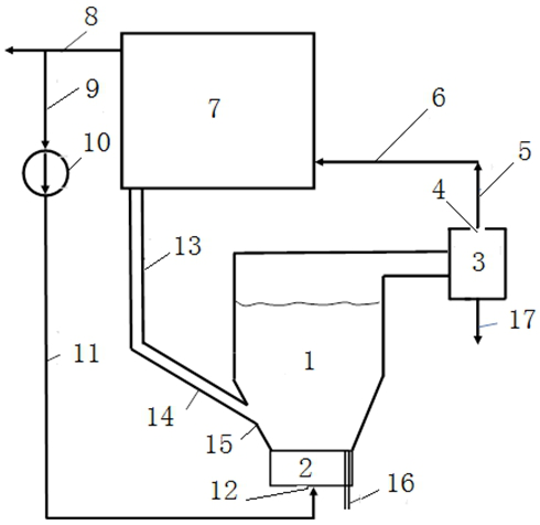
[0015] as attached figure 1 Described, implement a kind of coal-fired flue gas CO provided by the present invention above 2 The technical scheme of the solidified adsorption system mainly includes a bubbling adsorption bed system, a flue gas recirculation system and a slag discharge system; the bubbling adsorption bed system includes a bubbling adsorption bed 1, a fluidized air chamber 2, and a gas-solid separator 3. Smoke inlet 12, smoke exhaust port 4 and slag inlet 15; the flue gas recirculation system includes the outlet flue 8 of the economizer of the circulating fluidized bed boiler, the inlet pipe 9 of the flue gas recirculation fan, and the flue gas recirculation system. Circulating fan 10 and flue gas recirculation fan outlet pipe 11, bubbling adsorption bed system smoke exhaust pipe 5, circulating fluidized bed boiler secondary air pipe 6 and boiler 7; A slag pipe...


PUM


Abstract

The invention discloses a coal-fired flue gas CO2 curing adsorption system. The coal-fired flue gas CO2 curing adsorption system comprises a bubbling adsorption bed system, a flue gas recirculation system and a slag feeding and discharging system. The coal-fired flue gas CO2 curing adsorption system is characterized in that on the basis of the process advantages of medium-temperature combustion of a circulating fluidized bed boiler, calcination desulfurization of limestone in the boiler and medium-temperature slag discharging, slag discharging waste heat and CaO contained in the slag discharging waste heat are used for carrying out carbonation reaction to adsorb CO2, so that pollution is controlled by waste, the method is simple in process, low in cost and simple in process, cooperative treatment of the coal-fired solid waste and the flue gas CO2 is achieved, meanwhile, the carbon content of the fly ash of the CFB boiler is reduced, and the advantage that the circulating fluidized bed boiler controls coal-fired pollutants at low cost is further expanded.

Description

technical field [0001] The invention relates to a flue gas CO 2 Solidified adsorption systems, especially a circulating fluidized bed (CFB) boiler flue gas CO 2 Cured adsorption system. Background technique [0002] CO 2 Emissions reduction is a global issue, CO from burning coal 2 The emissions are relatively large, accounting for about 50-60%. 2 There are strict regulations on emission limits, but CO 2 Emission reduction is imperative. Currently, the CO under study 2 Emission reduction methods mainly include direct wet method, direct dry method and indirect wet method. Indirect wet method generally uses kinetic acid and kinetic alkali, which has serious secondary pollutants and high energy consumption. Direct wet method and direct dry method also consume high energy consumption. for CO 2 For large emitters-coal-fired power plants, these methods are used to remove CO 2 The cost is too high in the country for CO 2 These methods cannot be applied where emissions hav...

Claims


Application Information

Patent Timeline
IPC IPC(8): F23C10/24F23J15/02B01D53/12
CPCF23C10/24F23J15/02B01D53/12F23C2202/00F23C2206/10F23J2215/50Y02C20/40
Inventor 马素霞张建春王晓炜王娜娜朱俊平
Owner TAIYUAN UNIV OF TECH
Why Eureka
Try Eureka