
Power transmission line fault positioning method and system, electronic equipment and storage medium

A fault location and transmission line technology, applied in transmission systems, optical transmission systems, electromagnetic wave transmission systems, etc., can solve the problems of inaccurate fault location, long time to find and repair faults, and low fault location accuracy.

Inactive Publication Date: 2021-07-06
QINGYUAN POWER SUPPLY BUREAU OF GUANGDONG POWER GRID CO LTD
View PDF5 Cites 0 Cited by
  • Summary
  • Abstract
  • Description
  • Claims
  • Application Information

AI Technical Summary

Problems solved by technology

The accuracy of the existing fault location is low, and the fault location is not accurate, which leads to a long time to find and repair the fault, which has a great impact on the timely restoration of power supply

Method used


Image

  • Power transmission line fault positioning method and system, electronic equipment and storage medium
  • Power transmission line fault positioning method and system, electronic equipment and storage medium
  • Power transmission line fault positioning method and system, electronic equipment and storage medium

Examples


Embodiment 1

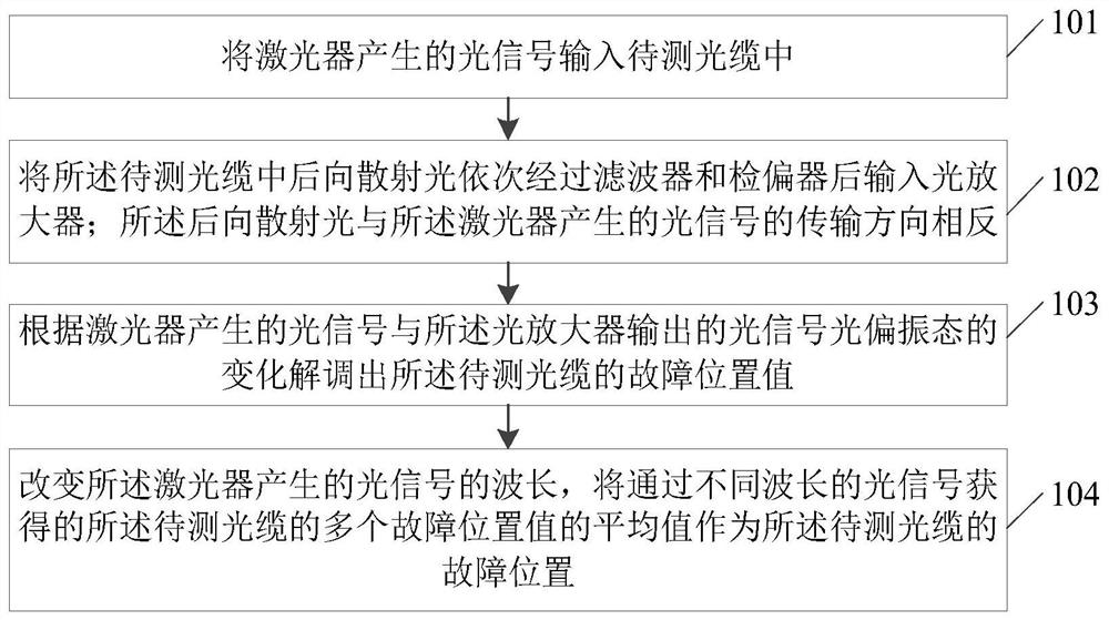
[0043] figure 1 The step-by-step flow chart of a transmission line fault location method provided by Embodiment 1 of the present invention, the embodiment of the present invention is applicable to the situation of monitoring the transmission line to determine the location of the fault, and the method can be implemented by the transmission line fault location system of the embodiment of the present invention To execute, the power transmission line fault location system can be implemented by hardware or software, and integrated in the electronic device provided by the embodiment of the present invention, specifically, such as figure 1 As shown, the transmission line fault location method in the embodiment of the present invention may include the following steps:

[0044] S101. Input the optical signal generated by the laser into the optical cable to be tested.

[0045] In the embodiment of the present invention, the laser can be an instrument used to generate an optical signal ...

Embodiment 2

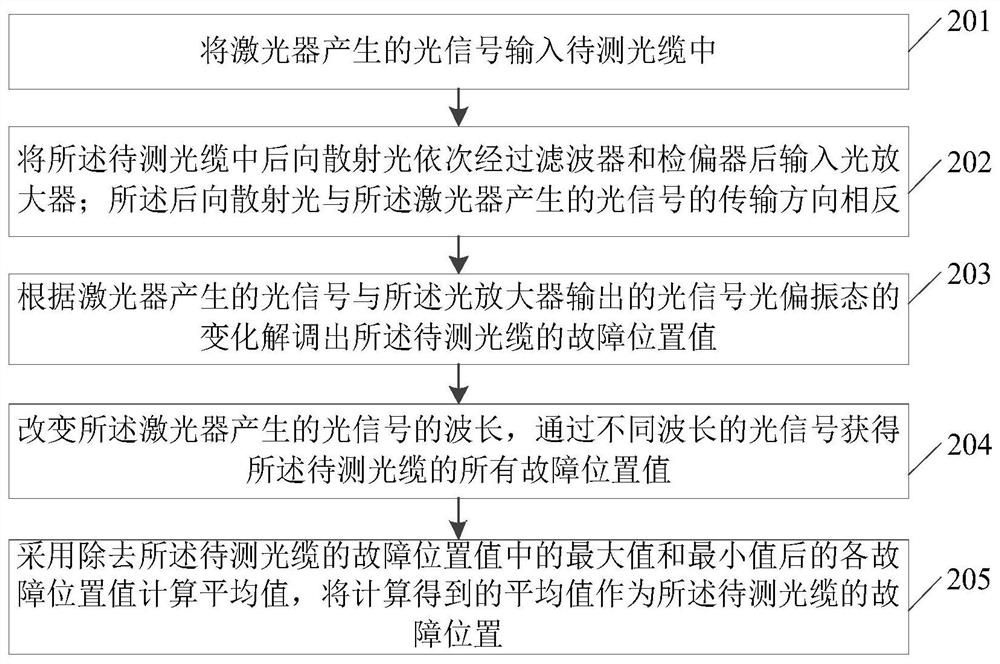
[0058] figure 2 It is a flow chart of the steps of a transmission line fault location method provided by Embodiment 2 of the present invention. The embodiment of the present invention is optimized on the basis of the above-mentioned Embodiment 1, as shown in figure 2 As shown, the transmission line fault location method in the embodiment of the present invention may include the following steps:

[0059] S201. Input the optical signal generated by the laser into the optical cable to be tested.

[0060] In the embodiment of the present invention, the laser can be an instrument used to generate an optical signal for testing. Preferably, the laser can be a tunable laser, which can adjust the wavelength of the generated optical signal, and generate an optical signal of a specified wavelength through the laser. , the optical signal is input into the optical cable to be tested through a circulator and / or a wavelength division multiplexer.

[0061] S202. Input the backscattered li...

Embodiment 3

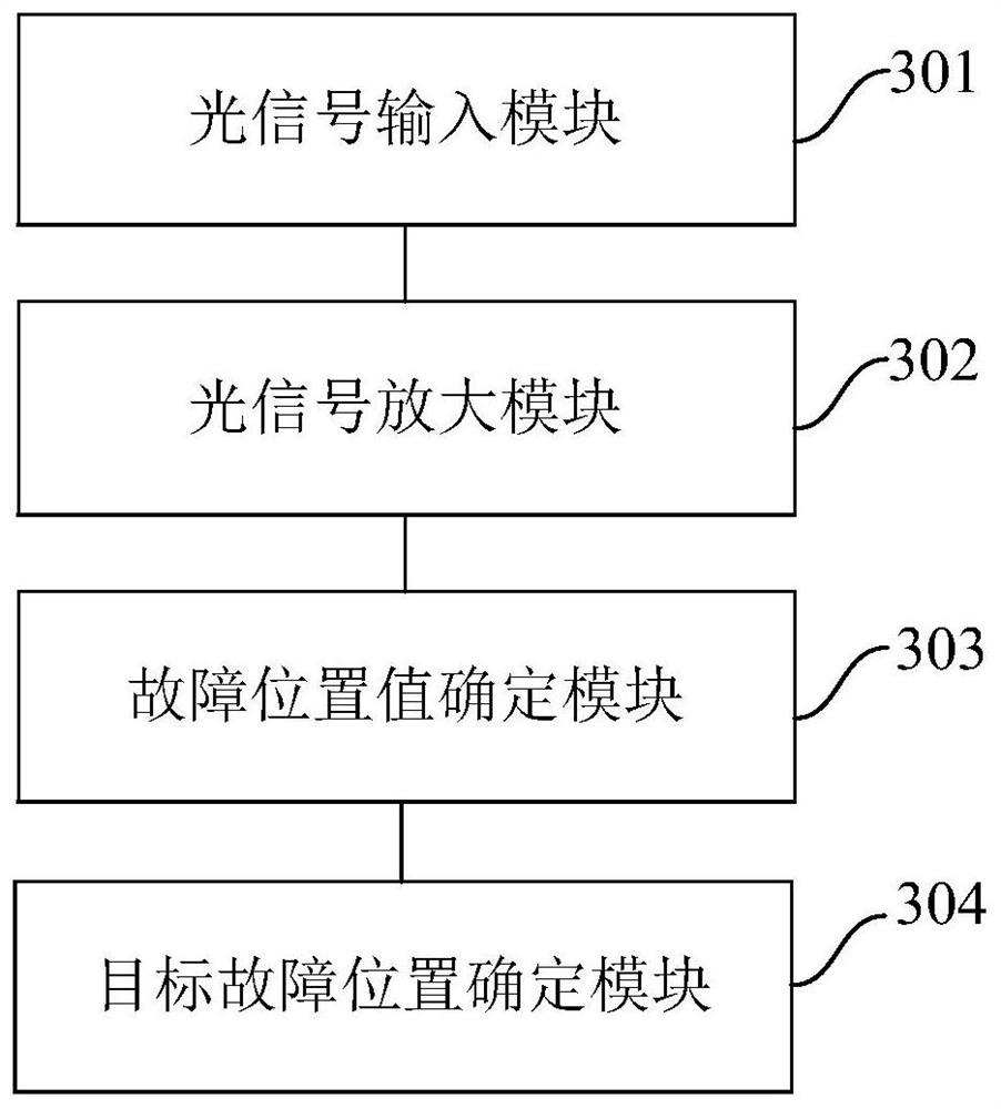
[0079] image 3 It is a structural block diagram of a transmission line fault location system provided by Embodiment 3 of the present invention, as shown in image 3 As shown, the transmission line fault location system in the embodiment of the present invention may specifically include the following modules:

[0080] An optical signal input module 301, configured to input the optical signal generated by the laser into the optical cable to be tested;

[0081] An optical signal amplification module 302, configured to input the backscattered light in the optical cable to be tested into the optical amplifier after passing through a filter and a polarizer in sequence; the transmission direction of the backscattered light is opposite to that of the optical signal generated by the laser ;

[0082] A fault position value determination module 303, configured to demodulate the fault position value of the optical cable to be tested according to the change in the optical polarization s...


PUM

PropertyMeasurementUnit
Isolationaaaaaaaaaa

Abstract

The embodiment of the invention provides a power transmission line fault positioning method and system, electronic equipment and a storage medium. The power transmission line fault positioning method comprises the following steps: inputting an optical signal generated by a laser into a to-be-detected optical cable; making backward scattered light in the to-be-detected optical cable pass through a filter and an analyzer in sequence and then input into an optical amplifier, wherein the transmission directions of the backward scattered light and the optical signal generated by the laser are opposite; demodulating a fault position value of the to-be-detected optical cable according to the change of the optical polarization state of the optical signal generated by the laser and the optical signal output by the optical amplifier; and changing the wavelength of the optical signal generated by the laser, and taking the average value of the plurality of fault position values of the to-be-detected optical cable obtained through the optical signals with different wavelengths as the fault position of the to-be-detected optical cable. According to the embodiment of the invention, the accuracy of fault positioning is improved, and the fault can be quickly searched and repaired through accurate fault positioning, so that power supply can be recovered in time.

Description

technical field [0001] The invention relates to the technical field of transmission line monitoring, in particular to a transmission line fault location method, system, electronic equipment and storage medium. Background technique [0002] Transmission line fault tripping is one of the most frequent accidents in the power grid. Transmission lines cross mountains and ridges, and are easily affected by various natural factors such as lightning, pollution, animals and plants, wind and dancing, and ice coating. Faults have a great impact on system security, equipment security, and power supply reliability. The accuracy of existing fault location is low, and fault location is inaccurate, resulting in a long time for finding and repairing faults, which has a great impact on timely restoration of power supply. Contents of the invention [0003] Embodiments of the present invention provide a transmission line fault location method, system, electronic equipment, and storage medium...

Claims


Application Information

Patent Timeline
IPC IPC(8): H04B10/071H04B10/077H04B10/80H04J14/02G06Q10/00G06Q50/06
CPCH04B10/071H04B10/0771H04B10/807H04J14/0227G06Q10/20G06Q50/06
Inventor 唐小亮黄绍川周亚兵张振何伟明杨芳潘斌尹文阔于文滔黄富勇王亮
Owner QINGYUAN POWER SUPPLY BUREAU OF GUANGDONG POWER GRID CO LTD
Learn More