Movable tensile shear stress rock breaking equipment system

A shear stress and mobile technology, applied in the field of mechanical rock breaking, can solve the problems of not resisting tensile shear, etc., and achieve the effects of being easy to master, protecting the environment, and solving low energy utilization rates

Active Publication Date: 2021-07-09
SINOSTEEL MAANSHAN INST OF MINING RES +2
View PDF12 Cites 0 Cited by
  • Summary
  • Abstract
  • Description
  • Claims
  • Application Information

AI Technical Summary

Problems solved by technology

[0005] In order to overcome the many disadvantages of rock breaking by explosive blasting, reduce the energy consumption of rock breaking by blasting, improve the utilization rate of rock breaking energy, create an excellent production and operating environment, and completely solve the blasting vibration, blasting dust and toxic and harmful gases induced by blasting rock breaking The present invention proposes a mobile tensile-shear stress rock-breaking equipment system. This equipment system makes full use of the rock mass’s characteristics of compressive resistance but not tensile-shear resistance. When the tensile stress and shear stress of the rock mass exceed its resistance When the tensile strength and shear strength are high, the rock mass can be broken into certain pieces, and the smaller tensile and shear stress can be used to achieve the purpose of breaking the rock mass, forming a new method of static environmental protection mechanical rock breaking

Method used


Image

  • Movable tensile shear stress rock breaking equipment system
  • Movable tensile shear stress rock breaking equipment system
  • Movable tensile shear stress rock breaking equipment system

Examples


Embodiment Construction

[0026] In order to better describe the present invention, a mobile tension-shear stress rock breaking equipment system of the present invention will be further described in detail below in conjunction with the accompanying drawings.

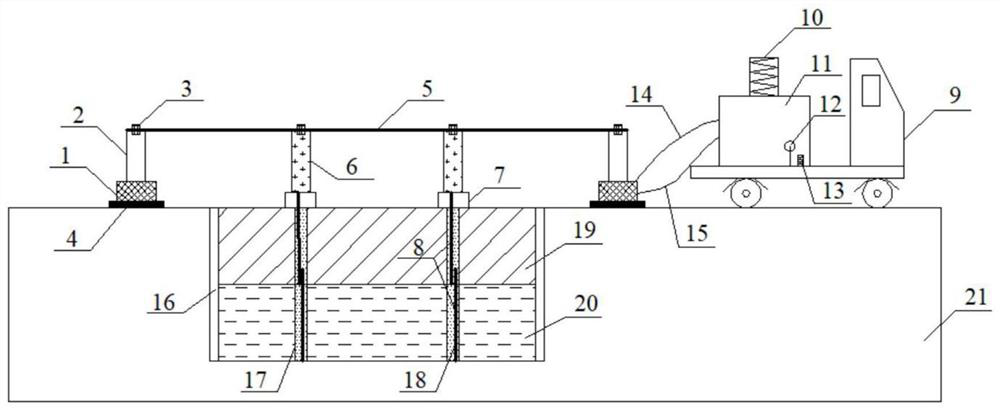
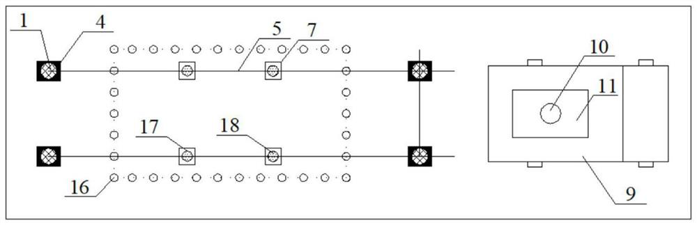
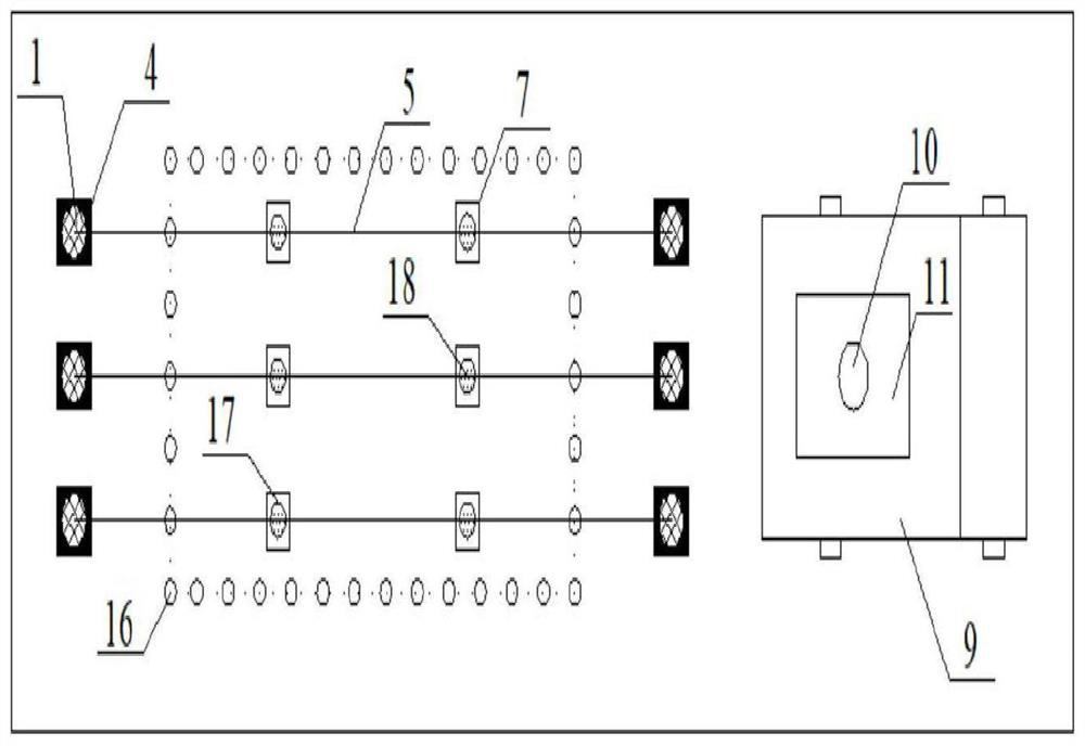
[0027] Depend on figure 1 Shown is a schematic diagram of a longitudinal section of a mobile tension-shear stress rock breaking equipment system of the present invention combined with figure 2 , image 3 It can be seen that a mobile tension-shear stress rock-breaking equipment system of the present invention is composed of a hydraulic power mechanism and a pulling-out rock-breaking mechanism connected by an oil delivery pipeline 14 and an oil return pipeline 1 .

[0028] Described hydraulic power mechanism comprises movable power car 9, the hydraulic oil tank 11 that is assembled on the power car 9, and hydraulic oil tank 11 is provided with driving motor 10, pressure gauge 12, the manipulator 13 that controls hydraulic oil tank 11 to send oil....


PUM


Abstract

The invention discloses a movable tensile shear stress rock breaking equipment system. A hydraulic power mechanism comprises a movable power vehicle (9) and a hydraulic oil tank (11), wherein the hydraulic oil tank (11) is assembled on the power vehicle (9), and a driving motor (10), a pressure gauge (12) and a controller (13) for controlling the hydraulic oil tank (11) to supply oil are arranged on the hydraulic oil tank (11); a drawing rock breaking mechanism comprises a hydraulic jack (1), a jacking vertical rod (2), a base plate (4), a cross rod (5), a drawing rod (6) and an anchoring rod (8); and one end of an oil feeding pipeline (14) and one end of an oil return pipeline (15) are respectively connected with an oil inlet and an oil return opening of the hydraulic jack (1), and the other end of the oil feeding pipeline (14) and the other end of the oil return pipeline (15) are respectively connected with an oil outlet valve and an oil return valve of the hydraulic oil tank (11). According to the movable tensile shear stress rock breaking equipment system, the characteristic that rock masses are resistant to pressure and are not resistant to tensile shear is fully utilized, static environment-friendly mechanical rock breaking with only drilling but not blasting is realized, the rock masses are prevented from being excessively smashed, the high boulder rate is avoided, the requirement for rock lumpiness of an engineering project is met, the mechanical shoveling and transporting efficiency is improved, and the shoveling operation cost is reduced.

Description

technical field [0001] The invention belongs to the technical field of mechanical rock breaking, and in particular relates to a mobile tension-shear stress rock breaking equipment system, which can be widely used in fields such as mines, tunnels, traffic roads, slopes, and foundation pit excavation. Background technique [0002] At present, explosive blasting is still the most important rock mass crushing method. However, the rock mass in the crushing area is too broken under the blasting rock crushing method, and large pieces are easy to be produced in the crack area, resulting in a low energy utilization rate of explosives, which is generally about 20%; and a large number of After the explosion energy is released, secondary disasters such as severe blasting vibration and noise are caused, and a large amount of blasting dust and CO, NO, NO 2 , NH 3 , SO 2 Blasting toxic and harmful gases, polluting the production environment and the atmospheric environment, seriously enda...

Claims


Application Information

Patent Timeline
Patent Type & Authority Applications(China)
IPC IPC(8): E21C37/08
CPCE21C37/08
Inventor 仪海豹李明李龙福江东平崔正荣
Owner SINOSTEEL MAANSHAN INST OF MINING RES
Why Eureka
Try Eureka